
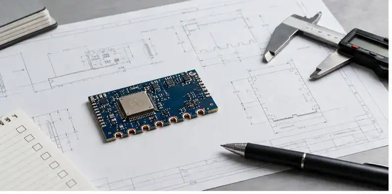
Quick Answer: PCB castellated holes requirements should state finished half-hole size, pad geometry, plating expectation, routing quality, panel support, surface finish, assembly use, and inspection evidence. The goal is a solderable module edge, not simply a row of cut-through vias.
Key takeaways – Define the castellated edge from the assembly interface backward. – Finished hole, copper wrap, pad width, and edge quality should be checked together. – Panelization and routing sequence can decide whether half-holes are clean or damaged. – Use DFM approval before production when the module will be soldered to another PCB.
Castellated holes look simple in a finished module, but they combine drilling, plating, routing, surface finish, and assembly fit. A buyer may ask for “half holes” and expect a solderable side terminal. A factory needs the dimensions, copper condition, and acceptance level that make the side terminal reliable.
This topic is useful for RF modules, IoT modules, small daughterboards, and test adapters that solder onto a carrier board. The risk is not only whether the board can be fabricated. The risk is whether the finished edge matches the carrier footprint and creates repeatable solder joints. Start with the normal PCB fabrication quote files, then add the castellated-hole requirements below.
Decision path
- Confirm the assembly role
- Define geometry and copper
- Control routing and panel support
- Decide finish and inspection evidence
- Close DFM questions before production
- Send a quote-ready package
- Practical approval path for castellated modules
Start with the module assembly role
A castellated edge exists because the module will connect to something else. That carrier board, socket, fixture, or soldering process should drive the requirement. If the module is hand-soldered for prototypes, the acceptance may be different from automated assembly. If it carries RF, power, or dense signal nets, pad geometry and wetting are more sensitive.
The buyer should state whether each half-hole is an electrical terminal, a mechanical alignment point, a test point, or a mix of these roles. A row that looks identical on the PCB may contain power pins, ground pins, RF nets, and no-connect mechanical features. Treating all of them as the same can create unnecessary risk.
For early supplier screening, use the broader PCB manufacturer capability check to confirm whether the supplier is comfortable with small plated half-holes, clean routing, and inspection expectations before a production schedule is promised.
Define hole size, pad geometry, and copper wrap
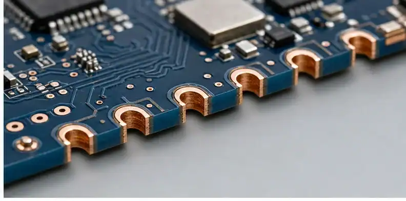
The finished half-hole size should match the mating footprint and solder process. State finished size rather than only drill tool size when the assembled fit matters. Plating reduces the hole diameter, routing removes half the barrel, and final edge quality decides how much copper remains available for solder wetting.
Dimension the module-to-carrier solder interface
Pad geometry matters as much as hole size. The land around the half-hole should support solder fillet formation and survive routing. If copper is too close to the cut, the half-hole may chip or expose uneven copper. If the pad is too small, the module may be hard to solder even if the board passes a basic visual check.
When a drawing and Gerber disagree, the supplier should stop and ask. That is a normal CAM-control issue, not a nuisance. The production record should say whether the drawing or data file controls the final half-hole geometry.
| Requirement | Why it matters | Typical evidence |
|---|---|---|
| Finished half-hole size | Controls mating footprint and solder volume | Drawing and drill table alignment |
| Pad width | Supports wetting and routing survival | Gerber review and DFM note |
| Copper wrap condition | Confirms solderable side terminal | Visual inspection or sample photo |
| No-connect features | Avoids unnecessary plating assumptions | Netlist and drawing note |
Control routing, tabs, and panel support
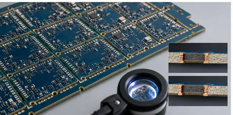
Castellated holes are usually drilled and plated before the board is routed through the holes. The panel must support the small module while the cut is made. If the panel design is weak, the routed edge can tear, burr, or leave uneven copper on the half-hole wall.
Keep the routed half-barrels mechanically supported
A buyer does not need to design the factory panel in detail, but should tell the supplier which edge must remain clean and whether small tab remnants are acceptable. For very small modules, discuss rail location, breakaway method, and whether array shipment is better for assembly.
Do not place mouse bites through functional castellations unless the supplier has explicitly confirmed the method. A small tab that is harmless on a rectangular FR-4 board can damage the most important feature on a castellated module.
Match surface finish and inspection to soldering risk
The surface finish should support the assembly method and shelf-life expectation. ENIG is often discussed for fine module edges, but the right answer depends on soldering process, cost, and reliability needs. The important point is to state whether the half-hole edge must be solderable and what evidence the buyer expects.
If shipment evidence matters, align the request with PCB quality documents before shipment. A small prototype may only need visual confirmation. A production module for a customer audit may need outgoing photos, sample inspection, or lot-level records.
Inspection should look at edge copper condition, burrs, breakout, finish coverage, and obvious plating defects. The supplier should not promise perfect cosmetic edges on an aggressive geometry unless the drawing and panel plan make that realistic.
| Risk | Buyer control | Supplier evidence |
|---|---|---|
| Poor side wetting | State solderable edge requirement | Sample photo or visual record |
| Copper tear-out | Review panel and routing approach | DFM approval before tooling |
| Burrs on module edge | Define acceptable edge quality | Outgoing inspection note |
| Misfit to carrier | Share carrier footprint | First-article fit check |
Close DFM questions before production starts
Castellated holes often trigger useful DFM questions: whether the pad is wide enough, whether the finished half-hole is achievable, whether the route line cuts through the correct hole center, and whether the surface finish is suitable. These questions are easier to solve before production than after a batch of modules is packed.
Use the PCB CAM questions process to classify each answer. A minor clarification can be answered quickly; a changed half-hole size, pad width, carrier footprint, or finish should become a controlled revision.
The buyer should also watch for silent substitutions. If the supplier proposes a simpler plated slot or edge pad instead of true castellated holes, decide whether that still fits the assembly requirement. The alternative may be valid, but it should not happen invisibly.
Build the quote-ready castellated-hole package
A useful package includes the PCB data, fabrication drawing, finished half-hole dimensions, carrier-board footprint or mating requirement, surface finish, quantity, inspection expectation, and whether the modules should ship as individual boards or panels. If assembly will be performed later, state how the modules will be handled.
The best RFQ language is specific without over-prescribing the factory process. Say what the finished edge must do, which features are functional, what evidence is needed, and which file revision controls the order. Let the supplier propose panel details and raise DFM issues early.
When the data is ready, send it through QueenEMS contact and ask for a castellated-hole manufacturability review before quotation lock. That gives purchasing a comparable quote and gives engineering a safer release record.
| Package item | Why it belongs |
|---|---|
| Carrier footprint | Confirms assembly fit |
| Finished half-hole dimensions | Prevents drill/tool ambiguity |
| Surface finish | Controls solderability expectation |
| Shipment format | Protects small modules during handling |
Practical approval path for castellated modules
Start from the carrier board, not the module alone
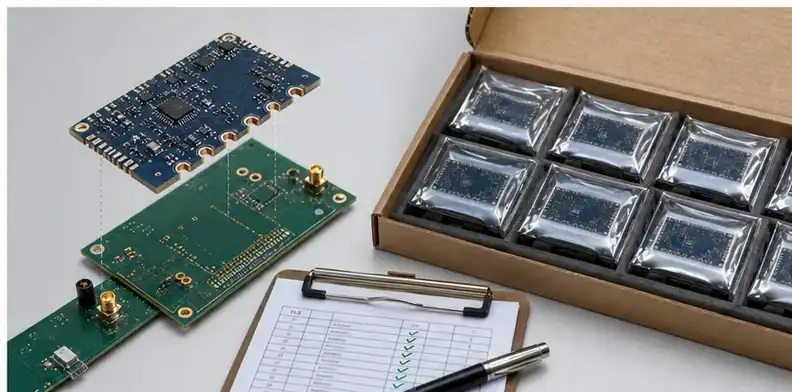
A castellated module is only successful when it works with the board it will be soldered onto. That means the buyer should review the module edge and carrier footprint together. Pad pitch, pad length, exposed copper, solder mask opening, stand-off expectation, and assembly process all influence whether the final joint is repeatable. If the module supplier sees only the module Gerbers, the quote may miss a fit issue that appears later at assembly.
For a new product, send the carrier footprint or at least the critical landing pattern. The supplier does not need the whole system design if it is confidential, but they need enough information to judge whether the half-hole geometry supports the solder joint. This is especially important when the castellated edge carries RF or high-current nets, because solder volume and ground continuity are part of the product performance.
Treat edge quality as an acceptance item
Castellated holes can be electrically connected and still look rough. The buyer should decide what edge quality is acceptable for the product. A development sample used for bench testing may tolerate more cosmetic variation than a module sold to a customer or assembled by automation. If the edge will be inspected by the end customer, sample photos or a first-article approval step can prevent a dispute.
Acceptance language should be practical. “Perfect half holes” is not a useful manufacturing requirement. Better wording identifies unacceptable conditions: broken copper that affects soldering, heavy burrs, loose laminate, missing plating in functional half-holes, or edge damage that prevents module seating. The supplier can then quote and inspect against visible risk rather than guessing the buyer’s cosmetic threshold.
Keep prototype decisions from leaking into production
Many castellated modules begin as urgent prototypes. A buyer may approve a wider tolerance, different panel method, or visual workaround to get samples quickly. That can be reasonable, but the approval should be marked as prototype-only when production will later require a cleaner edge. Otherwise the prototype shortcut becomes the silent production standard.
Before moving to production, review whether the prototype process, finish, panelization, and inspection method will remain the same. If the supplier plans to change the array, routing method, or shipment format, the buyer should ask whether the half-hole edge will look and solder the same. This is a small conversation compared with the cost of discovering that production modules no longer assemble like the approved sample.
Questions that separate real capability from a quick yes
Before accepting a quote, ask how the supplier will protect the half-hole edge during routing, whether the finished half-hole size is quoted from the drawing or inferred from drill data, whether the panel method can support the module size, and what evidence will show edge quality. These questions turn a broad capability claim into a production plan.
Also ask whether the supplier sees any conflict between the carrier footprint and the module edge. If the supplier cannot review the carrier footprint because it was not provided, record that limitation. A quote can still proceed, but the buyer should understand that the assembly fit has not been fully reviewed. For modules that will be sold as products, that limitation matters.
How to compare two castellated-hole quotations
Two quotes may differ because one supplier includes first-article photos, tighter edge-quality control, or array shipment while another assumes individual boards with minimal evidence. The buyer should not force both suppliers into the same price box without understanding scope. A cheaper price may be fine for a prototype, but production modules need repeatable solderability and edge quality.
Compare the finished half-hole requirement, panel/shipment method, surface finish, inspection scope, and DFM assumptions. If a supplier suggests a different pad size or route path, ask whether the change affects the carrier footprint. If it does, engineering should approve it before purchasing treats the quote as final.
What QueenEMS should confirm before draft production
A good review should confirm that the castellated edge is visible in the data, that half-hole size and pad geometry are not contradictory, that functional edges are protected in panel planning, and that the requested evidence matches the order risk. If questions remain, QueenEMS should raise them before tooling rather than smoothing over the uncertainty.
Wording that prevents a weak production release
Use RFQ wording that names the finished module function. For example, “castellated edge for soldering to carrier PCB, finished half-hole geometry per drawing, supplier to confirm routing and edge quality before production” is stronger than “make half holes.” If the assembly house needs modules shipped in panel, include that requirement before quotation. If the carrier footprint is preliminary, label it preliminary so the supplier does not treat it as frozen production data.
The final release should also say what happens to open DFM questions. If the supplier asks to change pad size, route position, or finish, the order should hold until engineering approves the effect on assembly. This keeps the module, carrier board, and production record aligned.
Approval record for reorders and supplier comparison
Repeat module orders depend on locked interface geometry more than on a quick second quote. Archive the carrier-footprint revision, castellated hole and pad relationship, profile centerline, panel delivery format, approved edge sample, and every DFM clarification with the module release. Purchasing can then tell whether a reorder is truly equivalent or whether a carrier or panel change requires another interface review.
Compare castellated-hole quotations against the same module interface, not against one board price. The response should state the finished half-hole geometry, outline-to-hole relationship, surface finish, panel or array format, shipment condition, and whether first-article edge images are included. A supplier quoting individual loose modules is carrying a different handling and routing assumption from one delivering assembly-ready arrays.
Before production release, overlay the module edge with the carrier footprint and confirm that every functional half-hole, pad and solder land uses the same revision. Then freeze the route centerline, finished geometry, surface finish and delivery format. A later change to the carrier land pattern or panel breakout should reopen the review even when the module Gerbers themselves have not changed.
FAQ
Should the board outline pass through each plated-hole center?
The fabrication data should show the intended routed half-hole geometry unambiguously. Put the outline, PTH drill data and copper pads in the same controlled release, then let the selected fabricator confirm its routing compensation rather than relying on an unlabeled edge cut.
Is continuous copper enough to accept a castellated edge?
No. Electrical continuity does not prove carrier fit, pad support, finish coverage, burr condition or solder access. Keep this requirements page focused on geometry and handoff, and use the castellated-hole acceptance page for finished-edge evidence.
What files should accompany a castellated-module RFQ?
Send Gerber or ODB++, plated drill data, the fabrication drawing, carrier footprint, module orientation, surface finish, shipment format and any first-article evidence request. Identify whether the modules will be hand soldered, reflowed as an SMT module, or installed by another controlled process.
For a castellated-module review, send QueenEMS the module fabrication package, carrier landing pattern, finished half-hole callout, finish, and desired array format. The returned DFM note should separate geometry changes from finished-edge acceptance evidence.
Written by the QueenEMS Engineering Team
Upload your files today · Free DFM check before production · Ship worldwide
Get your PCB prototypes in as fast as 24 hours. We handle FR4, Rogers, and Flex up to 60 layers — free prototypes for 2–4 layer boards, no minimum order.
Just upload your Gerber + BOM — we source every part, assemble, and inspect (AOI + X‑Ray) so you don't have to chase suppliers. Boards ship in as fast as 24 hours.