
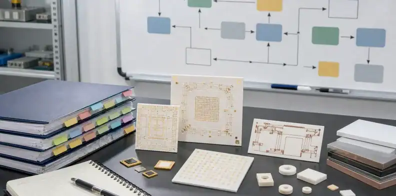
Struggling to Find a Reliable Ceramic PCB Manufacturer?
We understand that sourcing specialized circuit boards is challenging. QueenEMS bridges the gap between complex engineering requirements and reliable manufacturing execution.
Quote Response Within 2 Hours
We respond to ceramic PCB RFQs within 2 hours. Engineering review then confirms the material, process route, inspection scope and production schedule against the released files.
Consistent Batch Quality
The released material, stackup, process route and inspection requirements stay tied to the same drawing revision from prototype through repeat production. This reduces uncontrolled changes between an approved sample and later lots.
Real Technical Support
Discuss drawing exceptions, material options and assembly requirements with QueenEMS before fabrication. Record the proposed resolution and the person responsible for approving each change.
Have a drawing exception to resolve before ordering?
Talk to an Engineering ExpertWhat is a Ceramic Substrate PCB & Why Does It Matter?
Ceramic printed circuit boards use ceramic base materials such as alumina or aluminum nitride. Their suitability depends on the named material, metallization and completed assembly. Heat dissipation, insulation, circuit geometry and joining requirements should be reviewed together.
Superior Thermal Conductivity
Ceramic can provide an electrically insulating heat path beneath the circuit. The selected grade, thickness, heat-flow area and interfaces determine its contribution. The Cree LED thermal management note explains why board conductivity alone does not establish junction temperature.
Thermal Expansion in the Assembly
Ceramic grades have different coefficients of thermal expansion. Copper and joining layers also affect the response of a metallized substrate. Compare the complete construction with the die and mounting arrangement; a ceramic material alone does not prevent joint fatigue.
Excellent High-Frequency
A ceramic PCB for RF, microwave and radar designs can provide stable dielectric behavior, low moisture absorption and a short thermal path when the material and metallization route match the frequency and power level. Review layout constraints with our RF application support before release.
High Electrical Insulation
The ceramic can contribute electrical insulation between conductors and a cooling surface. Working voltage, geometry, interfaces and test conditions must be evaluated for the assembly; a material dielectric-strength number alone does not establish safe system voltage.
What Materials Are Used in Ceramic PCBs?
Material selection begins with the required thermal, electrical and mechanical behavior. The following descriptions distinguish common candidates from specialized materials; they are not a declaration that every route is available for every order.
- Alumina (Al₂O₃): A candidate for metallized substrates in electronics. Grade, thickness, surface condition and the intended process need to be specified; purity alone does not establish the finished board performance.
- Aluminum nitride (AlN): Consider when its thermal properties help meet the complete assembly requirement. Compare named grades and the proposed copper construction, including handling, joining and inspection needs.
- Silicon nitride (Si₃N₄): A material used in AMB power substrates where mechanical and cycling requirements matter. Assess the particular grade and metallized construction rather than assuming one universal strength or lifetime.
- Beryllium oxide (BeO): A specialized material requiring an appropriate beryllium safety and processing framework. It is not included as a routine quoted ceramic PCB route on this page.
- Silicon carbide (SiC): The term can refer to semiconductor devices or specialized ceramic materials. Do not confuse a SiC power die with the electrically insulating ceramic substrate supporting it; properties and function depend on the material grade.
Alumina and AlN are the principal material paths discussed here. As a supplier example, Rogers curamik data give 24 W/(m·K) for its alumina and 170 W/(m·K) for its AlN at 20°C. These are named supplier values, not QueenEMS test results or universal material limits. Request a grade-specific review for your construction.
📘 New to ceramic PCBs? Our complete Ceramic PCB Guide covers types, materials, cost, and how to choose the right board.
Need a robust circuit board for your high-power device?
Request Ceramic PCB FabricationFR-4 vs Ceramic PCB: Engineering Comparison
Use the material data and manufacturing limits below as a starting point. The released drawing still controls the final stackup, copper, tolerances and inspection plan.
| Engineering Point | FR-4 PCB | Ceramic PCB |
|---|---|---|
| Base material and standard routes | Glass-reinforced epoxy laminate; 1–32 layer capability. | Al₂O₃, AlN, ZTA and Si₃N₄; DPC, DBC, AMB, thick film, LTCC and HTCC. DPC/DBC/AMB support single- or double-sided circuits; multilayer capability depends on the ceramic route. |
| Thermal conductivity | 0.30–0.45 W/(m·K) for standard FR-4 materials; Isola FR408HR is 0.40 W/(m·K). | Al₂O₃: typically 20–30 W/(m·K) at approximately 20°C, depending on purity and grade. AlN: 170–250 W/(m·K), depending on the selected grade. |
| Thermal expansion reference | FR408HR: X/Y 16 ppm/°C below Tg; Z-axis 55 ppm/°C below Tg and 230 ppm/°C above Tg. | Rogers curamik reference values at 20–300°C: Al₂O₃ 7.1 ppm/K; AlN 4.7 ppm/K. |
| Copper capability | Outer copper 1–30 oz; inner copper 0.5–30 oz, subject to the selected stackup and feature size. | DPC: 0.5–3 oz. DBC/AMB: 3–12 oz. |
| Finished hole and board size | Standard hole 0.20 mm; HDI 0.10 mm. Maximum board size up to 610 × 610 mm. | Minimum PTH/NPTH: 0.05 mm; maximum PTH aspect ratio 5:1. Standard maximum size 130 × 180 mm; larger dimensions after engineering evaluation. |
| Best fit | Cost-sensitive multilayer routing, dense interconnects and general electronic assemblies. | Power modules, high-power LEDs, laser/RF assemblies and compact packages that need an electrically insulating, high-conductivity substrate. |
Material-data basis: FR408HR values are named Isola laminate data; curamik CTE values are named Rogers ceramic data. QueenEMS ceramic manufacturing limits are shown in the table below. Evaluate the complete thermal path before changing board material—ceramic does not automatically eliminate cooling hardware or prove longer field life.
Send the intended material, copper weight, line/space, finished size and hole table for a construction-specific review.
Submit Your Gerber for ReviewCore Ceramic Materials: Alumina vs. Aluminum Nitride
Material selection should connect the thermal path, coefficient of thermal expansion, geometry and budget. Buyers comparing an AlN ceramic PCB manufacturer should also confirm ceramic grade, copper route, surface finish and inspection scope.
Alumina (Al2O3) Ceramic PCB
Alumina grade, thickness and surface preparation are reviewed against the circuit, joining method and inspection requirements. The quotation should identify the offered grade and any proposed alternatives.
AlN Ceramic PCB Manufacturer — High Thermal Conductivity Substrates
QueenEMS reviews AlN ceramic PCB production through DPC, DBC and AMB routes for IGBT and SiC power modules, high-power laser systems and RF assemblies where the thermal path is critical. The released construction must identify the AlN grade or thermal class, substrate thickness, copper route, surface finish and required inspection evidence; material and process suitability remain subject to engineering review.
Not sure which ceramic material fits your budget? Read our deep dive on choosing alumina vs AlN to cut LED costs.
Consult with Our Material ExpertsAdvanced Ceramic PCB Fabrication Processes
DPC, DBC and AMB describe different metallization routes. The quotation identifies the route proposed for the ceramic, copper, geometry, surface finish and acceptance plan. Availability and suitability are confirmed for the released construction.
DPC (Direct Plated Copper)
DPC uses a deposited seed system and copper plating to form the conductor construction. Review final copper thickness, pattern geometry, surface finish and any hole metallization with the selected route.
DBC (Direct Bonded Copper)
DBC bonds copper to ceramic through a high-temperature bonding process. Current capability and heat spreading depend on the finished conductor geometry and boundary conditions; the process name alone does not establish a safe current.
AMB Ceramic PCB (Active Metal Brazing)
An AMB ceramic PCB uses an active braze layer to bond copper to AlN or Si3N4. It is commonly evaluated for IGBT and SiC power modules that need high current, electrical isolation and project-specific thermal-cycle evidence.
Unsure which metallization process you need? Compare them in depth: DPC vs DBC and AMB vs DBC.
Get Free Engineering AdviceCeramic PCB Manufacturing Capabilities
The matrix below separates general production capability from advanced or special-process options. A released quotation confirms the exact material, conductor system, geometry, finish and inspection scope.
| Item | General Parameter | Special Process |
|---|---|---|
| Materials and Conductors | ||
| High insulation, chemical-corrosion resistance and high-temperature resistance | Al₂O₃ | Glass, quartz, sapphire, 99% Al₂O₃ and 92% black Al₂O₃ |
| High thermal conductivity, low thermal expansion and high-temperature resistance | AlN | Glass, quartz, sapphire, 99% Al₂O₃ and 92% black Al₂O₃ |
| Insulation performance and high-temperature stability | ZTA | Glass, quartz, sapphire, 99% Al₂O₃ and 92% black Al₂O₃ |
| High strength, high hardness, high thermal conductivity and low dielectric loss | Si₃N₄ | Glass, quartz, sapphire, 99% Al₂O₃ and 92% black Al₂O₃ |
| Conductor Systems | Tungsten (LTCC/HTCC), Au, Au–Pd, Au–Pb, Ag, Ag–Pd and Ag–Pb | Matched to the selected ceramic and firing route |
| Ceramic Manufacturing Routes | ||
| DPC | Single- or double-sided | — |
| DBC / DCB | Single- or double-sided | — |
| AMB | Single- or double-sided | — |
| Thick Film | Single-sided, double-sided and 4-layer | — |
| LTCC | Single-sided, double-sided, 4-layer and 6-layer | 6–14 layers |
| HTCC | Single-sided, double-sided, 4-layer and 6-layer | — |
| Inner Layer | — | — |
| Outer Copper | DPC: 0.5–3 oz; DBC/AMB: 3–12 oz | — |
| Dimensions, Holes and Tolerances | ||
| Maximum Dimension | 130 × 180 mm | Larger dimensions after evaluation |
| Minimum Dimension | 2 × 2 mm | Shipped in panel |
| Substrate Thickness | Al₂O₃ / AlN: 0.38, 0.635 and 1.0 mm; Si₃N₄: 0.25 and 0.32 mm | >1.5 mm |
| Minimum PTH | 0.05 mm | — |
| Minimum NPTH | 0.05 mm | — |
| Maximum Aspect Ratio (PTH) | 5:1 | — |
| NPTH Diameter Tolerance | ±0.05 mm | — |
| PTH Diameter Tolerance | ±0.05 mm | — |
| Outline Tolerance | ±0.05 mm | ±0.10 mm |
| Minimum PTH Tolerance | ±0.05 mm | ±0.10 mm |
| Minimum NPTH Tolerance | ±0.05 mm | ±0.10 mm |
| Minimum Circuit to Board Edge | 0.20 mm | 0.15 mm |
| Overall Thickness | 0.20–2.00 mm | ≥2.00 mm |
| Finished Board Thickness Tolerance | <1.0 mm: ±0.10 mm; >1.0 mm: ±10% | — |
| Surface Finish, Solder Mask and Legend | ||
| OSP | 0.20–0.50 µm | — |
| ENIG | Au 1–3 µin; Ni 120–320 µin | — |
| Immersion Silver | 6–12 µin | — |
| Immersion Tin | ≥1 µm | — |
| ENEPIG | Au 2 µin; Pd 1 µin; Ni 100 µin | — |
| Hard Gold | Au 5–30 µin; Ni 120–200 µin | — |
| Conductor Cover | Glass glaze, dielectric medium or solder mask ink | — |
| Solder Mask Color | White, black or green | Mixed/custom color |
| Silkscreen Color | White or black | Mixed/custom color |
| Silkscreen Feature | Line width ≥0.13 mm; character height ≥0.8 mm | — |
| Solder Mask Thickness | ≥20 µm | — |
| Solder Mask Bridge | ≥0.15 mm | 0.10 mm |
| Additional Confirmed Capabilities | ||
| Volume-Production Materials | Al₂O₃ and AlN | — |
| Volume-Production Routes | DPC, DBC and AMB | — |
| Thermal Conductivity | Al₂O₃: typically 20–30 W/(m·K) at approximately 20°C; AlN: 170–250 W/(m·K) | Actual value depends on the selected material purity and grade; it is not a finished-board thermal-performance guarantee |
| Lead-Free HASL | 2–40 µm | — |
| Electroless Nickel | 2–7 µm; phosphorus 8% ±2% | — |
| Prototype Lead Time | 3 weeks | 2 weeks expedited |
| Volume Production Lead Time | 2–3 weeks after construction and order release | Special materials or dimensions scheduled after review |
| Compliance Documentation | RoHS-compliant material and finish options | Declaration scope confirmed against the ordered construction |
Mark the ceramic, process, conductor, copper, holes, outline, finish and tolerances in the drawing so engineering can confirm the exact released construction.
Upload Gerber for Feasibility CheckCeramic PCB Assembly Service — From Bare Substrate to Finished Module
QueenEMS coordinates ceramic PCB fabrication with optional SMT assembly for Al2O3, AlN and Si3N4 constructions. The assembly route is reviewed against the released substrate, copper structure, placement data, thermal profile, inspection scope and test requirements before production.
Ceramic-Specific Assembly Controls
Ceramic substrates require tighter handling, board support, flatness control and thermal-profile review than ordinary FR-4. Engineering confirms the soldering or attachment route, component and substrate constraints, inspection method and acceptance evidence for the released build.
Files for a Buildable Ceramic PCBA Review
Send the Gerber or ODB++ package, fabrication drawing, BOM, placement data, assembly drawing, quantity and required test scope. QueenEMS will identify missing inputs and return fabrication-and-assembly questions against one controlled file revision.
Submit the fabrication and assembly package for one coordinated engineering review.
Request Ceramic PCB Assembly ReviewCeramic PCB Application Reviews
Custom ceramic PCB applications span power conversion, RF and microwave, LED, industrial control and medical electronics. The material and copper route should be selected from the actual heat, frequency, voltage and mechanical requirements.
EV & Automotive
AMB and DBC substrates for IGBT and SiC power modules. IGBT ceramic substrate design and test review
High-Power LED
Stage lighting and UV curing systems.
Aerospace & RF
Ceramic PCB for RF, microwave, radar and telecom modules.
Industrial Control
Heavy machinery and laser transmitters.
Medical Devices
CT scanners and precision surgical tools.
Building for a demanding industry?
IGBT ceramic substrate design and test reviewHow Much Does a Ceramic PCB Cost? Pricing Factors & DFM Tips
Cost-effective ceramic PCB manufacturing comes from matching Al2O3 versus AlN, the DPC, DBC or AMB route, standard thicknesses, copper requirements, geometry, inspection and quantity to the actual thermal and reliability target—not from forcing every design into the lowest-price process.
What Drives the Cost?
Price depends on the accepted deliverable, construction, quantity and inspection scope. Compare written quotations for the same requirements. The main items to review include:
- Base material: Compare the offered grades and any required polishing or preparation. Evaluate alternatives against the same thermal and mechanical requirements before approving a substitution.
- Geometry: Outline, holes, cutting allowances, support and delivery format affect the production plan. Ask how a proposed drawing change affects manufacturability and the quote.
- Metallization: Compare the complete copper and interface construction. Do not infer selling price from process temperature or assume a fixed DPC, DBC or AMB cost order.
- Acceptance scope: Include required inspection, test samples and reporting in the comparison. Avoid assigning an assumed factory yield to a design without relevant production records.
How to Reduce Your Costs (DFM)
Before you send your PO, our engineers review your Gerber files to implement cost-saving optimizations:
- Available thickness: Ask which ceramic and copper combinations are available for the proposed route. Review any change to thermal performance, insulation and fit before choosing an alternative.
- Hole requirements: Distinguish clearance holes, plated holes, filled vias and other openings. Use construction-specific geometry limits rather than a universal minimum hole size.
- Panelization: Ceramic panelization is evaluated case by case based on substrate material, thickness, dimensions, edge clearance, handling and separation method. We confirm whether panel or single-piece delivery is more suitable before quotation.
- Copper construction: Specify the finished thickness and current path in dimensions meaningful to the process. Review heat spreading, conductor geometry and mechanical effects before reducing copper.
Before freezing the quoted material route, compare the ceramic PCB price breakdown with the alumina-versus-AlN cost guide.
Request a Free DFM Analysis3 Hidden Traps When Sourcing Ceramic PCBs
Supplier approval should connect the quoted construction with relevant material, inspection and change-control evidence. These three checks help identify gaps before release.
Trap 1: Poor Copper Adhesion
A copper separation can involve bonding, contamination, geometry, handling or assembly conditions. Confirm the interface and test method before attributing a cause. Adhesion requirements should include specimen geometry and test conditions.
The QueenEMS Solution
The agreed inspection plan should state the adhesion or cycling evidence required, its sample construction and acceptance conditions. A process label or a pass/fail claim without those details cannot establish application suitability.
Trap 2: Fake Material Specs
A broad material name can hide a grade or construction mismatch. Match the quoted grade to the drawing and required documentation rather than assuming all AlN or alumina products share one property value.
The QueenEMS Solution
Request the material identification and records included with the order, and confirm how they connect to the delivered lot. The IGBT ceramic substrate design and test review explains how to distinguish material data from finished-module evidence.
Trap 3: Inconsistent Mass Production
A change between prototype and production can invalidate an earlier comparison. Record the approved material, site, process route, assembly interfaces and inspection plan, and define which changes require another review.
The QueenEMS Solution
Controlled process documentation. The released material, metallization route, inspection scope and revision are carried from prototype into repeat production, with deviations returned for approval before the build proceeds.
Don't risk your product's reputation on unverified suppliers. Use our checklist: 8 key questions to evaluate a ceramic PCB manufacturer.
Partner with a Verified ManufacturerCeramic PCB Prototype Production and Lead Times
Standard ceramic PCB prototypes are scheduled for 3 weeks, with a 2-week expedited option. Production is scheduled for 2–3 weeks after the material, process route, released files, inspection scope and assembly requirements are confirmed.
Rapid Quotation
After File Review
Engineering reviews the Gerber or ODB++ data, drawing, material route, quantity and inspection scope before price and schedule are confirmed.
Quick-Turn DPC Ceramic PCB Fabrication
3 Weeks Standard / 2 Weeks Expedited
Standard DPC ceramic PCB prototypes are scheduled for 3 weeks, with a 2-week expedited option when the Gerber or ODB++ package, drawing, Al2O3 or AlN material, copper requirement, finish, inspection scope and production slot are confirmed.
Low/Mid Volume
2 - 3 Weeks
Pilot and low/mid-volume production is scheduled for 2–3 weeks after the approved revision, material route and inspection plan are confirmed.
Mass Production
2 - 3 Weeks
Mass-production lead time is 2–3 weeks after the released construction, panel plan, inspection scope and order quantity are confirmed.
Facing a tight deadline for your critical project?
Plan Your Ceramic PCB ProductionWhy Choose QueenEMS as Your Ceramic PCB Manufacturer?
Buyers comparing ceramic PCB suppliers should verify who controls material selection, the DPC, DBC or AMB route, revision handoff, inspection scope and prototype-to-production release before comparing unit price. QueenEMS combines fabrication review with direct engineering communication so those quotation assumptions remain visible before tooling.
Direct Factory Sourcing
The quotation should identify the scope of fabrication and assembly, production responsibilities and any externally supplied steps. Clear responsibility helps keep the approved drawing and inspection requirements connected to the delivered order.
Process-Specific Equipment
Laser drilling, DPC plating and DBC bonding routes are reviewed against the ceramic, copper, geometry and inspection requirements of the released design.
Engineering-Led Support
Our online service team bridges the gap between sales and engineering. You receive transparent technical answers and proactive DFM advice, not just blind order-taking.
Global Export Reliability
Confirm the delivery country, packaging requirements, commercial terms and compliance documents during quotation. These details make the shipping and documentation scope clear before the order is released.
Ready to upgrade your PCB supply chain?
Contact Our Experts DirectlyCeramic PCB Electrical & Process Inspection
Inspection is defined by the ceramic substrate, circuit structure, order quantity and approved quality requirements. We select flying-probe or bed-of-nails electrical testing and combine it with the process checks required by the released drawing and inspection plan.
Flying-Probe or Bed-of-Nails Testing
Electrical testing is selected according to board construction and production volume, with the test method and acceptance requirements tied to the released lot and revision.
AOI & Conductor Geometry Inspection
AOI and dimensional inspection verify visible circuitry and specified geometry, including conductor width, conductor spacing and other drawing-controlled features.
Adhesion, Plating & Warpage Checks
The inspection plan can include copper adhesion, plating thickness, warpage and other project-specific checks defined by the structure and application. Applicable IPC requirements are documented when included in the quoted inspection scope.
Want to verify our capabilities?
Request Sample Inspection ReportsFrequently Asked Questions (FAQ)
Get immediate answers about our Ceramic PCB fabrication, assembly services, and ordering processes.
Why choose Ceramic PCBs (Al2O3/AlN) over standard Metal Core PCBs (MCPCBs) for thermal management?
Are Ceramic PCBs capable of supporting high-frequency/RF signals?
How much does a ceramic PCB cost compared to FR4?
Can you manufacture multilayer ceramic PCBs?
How do Ceramic PCBs perform in extreme temperature and chemically aggressive environments?
What is the lead time for ceramic PCB prototypes?
The standard lead time for a ceramic PCB prototype is 3 weeks. An expedited prototype can be completed in 2 weeks. Both schedules start after engineering confirmation, including DFM review approval, released files, material confirmation, surface finish and inspection scope. Mass production is scheduled for 2–3 weeks after the production construction and order requirements are confirmed.
What is the long-term ROI of investing in Ceramic PCB technology for our product line?
What is the Minimum Order Quantity (MOQ) for Ceramic PCBs?
Do you offer Ceramic PCB Assembly (Turnkey PCBA) services?
What files do I need to provide for a quotation?
For bare Ceramic PCBs, please provide standard Gerber files (RS-274X format) or ODB++ files, along with a Readme text file detailing material thickness, copper weight, and surface finish. If you need Assembly (PCBA), please also include a detailed BOM (Bill of Materials) in Excel format and Pick & Place coordinates.
Can you manufacture Ceramic PCBs with blind or buried vias?
Have a specific technical question about your design?
Ask Our Engineering TeamReady to Start Your Ceramic PCB Project?
Upload the Gerber or ODB++ files, drawing, target material, copper requirements, quantity and assembly scope. Engineering will return construction-specific DFM questions and a quotation based on the reviewed requirements.
Email Us
Email QueenEMS
Response after engineering review
Call / WhatsApp
+86 755 36309132
Mon - Sat, 9AM-6PM CST
Visit Our Office
1/27, Soi Border 5, Bang Bon Tai, Bang Bon, Bangkok 10150, Thailand
Visit Our Factory
Shenzhen, China (Verified Facility)