

Quick Answer: A PCB manufacturer capability check compares your complete board construction with the supplier’s normal production route across 12 inputs: layers, stack-up, dimensions, trace/space, holes, vias, copper, laminate, impedance, finish, mechanical features, and volume. Classify every critical input as routine, engineering-review, change-required, or unsupported before requesting a production quotation.
Key takeaways – A capability table screens suppliers; it does not approve your exact board. – Check combinations such as finished hole, board thickness, copper, and stack-up—not isolated minimums. – Ask the supplier to return a proposed construction, open questions, and approval items. – Leave commercial and quality qualification to their dedicated supplier-selection steps.
The practical question before an RFQ is not whether a factory makes “multilayer PCBs.” It is whether the proposed material set, geometry, hole structure, tolerances, panel, and volume fit one controlled manufacturing route.
This guide provides a board-level capability check for engineers and buyers. It deliberately stays narrower than the broader guide on how to choose a PCB manufacturer, which also covers certifications, supplier risk, commercial comparison, and qualification orders.
Table of Contents
- What Does a Capability Check Decide?
- Which Board Inputs Should You Send First?
- How Do Layer Count and Stack-Up Affect Capability?
- How Should Trace, Space, and Copper Be Checked?
- How Do Hole Size and Thickness Interact?
- When Do Blind and Filled Vias Need Review?
- How Should Materials and Impedance Be Matched?
- Which Finish and Mechanical Features Matter?
- What Evidence Should the Manufacturer Return?
- How Do You Turn the Check Into an RFQ?
What Does a Capability Check Decide?
A capability check decides whether a particular board can move into quotation unchanged, needs engineering review, needs an approved design change, or should be placed with another process route. It is an early technical disposition, not a complete supplier approval.
Use four outcomes:
| Disposition | Meaning | Buyer action |
|---|---|---|
| Routine | The complete feature combination fits the supplier’s stated normal production route | Continue to controlled file review |
| Engineering review | The supplier needs stack-up, CAM, material, panel, or process confirmation | Close named questions before relying on price or lead time |
| Change required | The current design is not recommended, but a defined modification could make it producible | Review electrical, mechanical, reliability, cost, and schedule impact |
| Unsupported | The supplier does not recommend the construction or lacks the required route | Select another qualified process or supplier |
Do not treat “yes, we can build it” as the final result. Require the supplier to identify the assumptions behind the answer. A multilayer board may be routine with one copper weight and hole structure but require a different press cycle, drill route, or inspection plan when those inputs change.
A capability check also does not prove regulatory compliance, quality-system suitability, repeatability, capacity, delivery performance, or after-sales support. Those topics belong in supplier qualification. Keeping the boundary clear prevents a technical screening page from becoming another generic manufacturer-selection article.
Which Board Inputs Should You Send First?
Send a structured specification summary before—or together with—the controlled manufacturing data. The summary helps the supplier locate the features most likely to determine process fit.
Use these 12 inputs:
- layer count and proposed stack-up;
- finished board dimensions and array constraints;
- overall thickness and local thickness restrictions;
- minimum finished trace width and spacing by copper layer;
- copper weights, including heavy-copper areas;
- smallest finished hole and drill type;
- through, blind, buried, filled, capped, back-drilled, or castellated features;
- laminate designation or electrical/thermal performance requirements;
- controlled-impedance targets and tolerance;
- surface finish and special plating;
- dimensional, routing, scoring, edge, cavity, coin, or other mechanical features;
- prototype, pilot, and expected production quantities.
Also state the destination country and product stage. Volume can influence panel strategy, tooling, sampling, and whether a process that is acceptable for an engineering lot is sensible for repeat production.
For an initial confidential review, you can remove net names, component data, and other sensitive information while retaining the board geometry and construction parameters. The result remains provisional until the supplier’s CAM team reviews controlled data.
Do not copy website capability values into your drawing. Your drawing should state product requirements. The manufacturer should explain how its process meets them or propose a controlled alternative.

How Do Layer Count and Stack-Up Affect Capability?
Layer count is only the visible label. The actual capability depends on dielectric thicknesses, copper distribution, material system, press cycles, registration, impedance requirements, hole structures, and finished thickness.
Ask the supplier to propose or confirm:
- core and prepreg arrangement;
- copper weights before and after processing;
- target and tolerance for finished thickness;
- finished dielectric targets used for impedance modeling;
- lamination sequence and whether sequential lamination is required;
- material manufacturer, grade, availability, and substitution rule;
- copper balance or thieving changes that need approval;
- coupon and panel requirements.
Two 8-layer boards can require very different processes. One may use conventional through holes and standard dielectric spacing. Another may combine thin dielectrics, heavy copper, buried vias, blind microvias, tight impedance, and a restricted overall thickness. A supplier’s maximum layer count says little about whether both are routine.
If the manufacturer owns stack-up design, define the electrical and mechanical interfaces they must preserve. If you own it, ask for a DFM confirmation before release. In either case, capture the approved version in the fabrication package.
For standard multilayer work, review the proposed route against the multilayer PCB manufacturing service. If sequential build-up is required, use the HDI PCB design decision guide to confirm that HDI is justified rather than added by accident.
How Should Trace, Space, and Copper Be Checked?
Check minimum trace and spacing by layer, copper weight, feature length, and surrounding geometry. A single website minimum usually describes a best-case or defined process condition; it may not apply to heavy copper, long parallel features, large panels, or the required tolerance.
Ask the CAM review to identify:
- the actual minimum drawn and finished conductor widths;
- minimum copper-to-copper, copper-to-hole, and copper-to-edge clearances;
- layers and locations where the minimum occurs;
- starting and finished copper assumptions;
- whether etch compensation changes finished geometry;
- annular-ring and pad requirements after registration allowance;
- solder-mask web, dam, and clearance constraints;
- any local features that need redesign.
Do not add an arbitrary safety percentage to every design rule. Margin should reflect the supplier’s controlled process, the feature, the inspection method, and the product requirement. A useful response states the recommended production rule and the reason it differs from the layout.
Heavy copper and fine spacing often work against each other because the copper thickness changes the etching challenge. Likewise, a short isolated neck-down may receive a different review from a long impedance-controlled trace. The manufacturer should evaluate the actual data rather than approve a specification summary alone.

How Do Hole Size and Thickness Interact?
Finished hole size must be checked with board thickness, drill diameter, plating allowance, hole type, material, and required copper in the hole. This relationship is often summarized by aspect ratio, but the supplier still needs the complete construction.
For each critical hole, provide:
- finished diameter and tolerance;
- plated or non-plated status;
- board thickness or relevant dielectric span;
- mechanical or laser drill requirement;
- via, component lead, press-fit, mounting, slot, or other function;
- fill, cap, planarization, or plugging requirement;
- pad and antipad geometry;
- applicable acceptance and test requirements.
Do not compare a finished-hole requirement directly with a website’s drill-tool minimum. Fabrication may start with a larger drill to allow for plating. The supplier should distinguish tool size, finished size, and tolerance.
Ask whether the hole is routine for the proposed thickness and production volume. If not, the options may include increasing the finished hole or pad, reducing thickness, changing the via structure, using a different drill route, or changing the stack-up. Any option requires electrical and mechanical review before approval.
Press-fit holes deserve separate control because the finished diameter, plating, connector specification, and measurement method are linked. Slots, countersinks, counterbores, castellations, and edge holes also need explicit drawings and tolerances.
When Do Blind and Filled Vias Need Review?
Blind, buried, microvia, stacked, staggered, filled, capped, and back-drilled structures need review whenever their geometry or sequence changes the lamination, drilling, plating, filling, planarization, or inspection route.
Describe the via by start and stop layer, finished geometry, pad sizes, fill type, cap requirement, and function. Do not rely on a generic note such as “VIPPO” without a drawing or layer definition.
Review these interactions:
| Via feature | Capability question |
|---|---|
| Blind/buried span | Does the layer pair fit the proposed lamination sequence? |
| Microvia diameter and depth | Is the geometry supported for the selected dielectric and capture pads? |
| Stacked structure | How are alignment, fill, and reliability controlled? |
| Via-in-pad | Is conductive fill, cap plating, and planarization required? |
| Back drill | What stub target, tolerance, access, and verification apply? |
| Filled through hole | Which fill material, fill condition, cap, and surface planarity are required? |
The supplier should flag when a structure is theoretically possible but not recommended for the requested volume or reliability objective. Ask what evidence will be used: process qualification, microsection, coupon, X-ray, electrical test, or other agreed record.
The HDI PCB DFM checklist provides a layout-level review for build-up boards. Keep the final approved via structure in the stack-up and fabrication drawing so it cannot change during quoting.

How Should Materials and Impedance Be Matched?
Match materials by the properties required by the electrical, thermal, mechanical, assembly, safety, and reliability design. Matching only a nominal Tg value or the broad label “FR-4” does not establish equivalence.
State whether the material is:
- an exact manufacturer and grade;
- one of several approved grades;
- supplier-proposed against documented property limits;
- subject to customer approval for every substitution.
For impedance, provide target values, tolerance, layer/reference relationship, trace type, and whether the manufacturer may adjust trace geometry. The supplier needs stack-up, dielectric, copper, and finished geometry information to model a producible construction.
Ask the manufacturer to return the proposed material set, finished dielectric targets, modeled geometry, coupon approach, and reporting requirement. If a geometry adjustment is proposed, define who approves it and how the final manufacturing data will record the change.
The controlled-impedance PCB guide covers targets, stack-up communication, coupons, and reports in more depth. A capability check should reference that owner rather than reproduce a full impedance-design tutorial.
When material availability is uncertain, request a separate quoted option. Do not allow a supplier to replace a controlled material silently after the technical review.
Which Finish and Mechanical Features Matter?
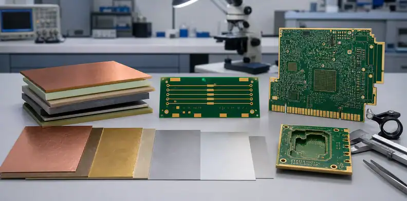
Surface finish and mechanical features matter when they introduce a special process, restricted supplier, tight tolerance, handling risk, or inspection requirement. Include them in the capability check even if they occupy only a small area.
Review:
- ENIG, ENEPIG, immersion silver, immersion tin, OSP, HASL, hard gold, or another defined finish;
- selective or mixed finishes;
- edge connectors and controlled gold thickness;
- plated edges, castellations, edge holes, or wrap plating;
- controlled-depth routing, cavities, countersinks, or counterbores;
- V-score, routing tabs, breakaway rails, and panel restrictions;
- coins, heat spreaders, embedded features, or unusual metal structures;
- board flatness, bow/twist, local thickness, and critical dimensions.
State which standard, drawing, or component interface defines the requirement. Avoid specifying a narrow tolerance without explaining the mating, enclosure, connector, or assembly need. The manufacturer may propose a more producible tolerance, but the design owner must evaluate its impact.
Ask whether the process is performed at the quoted site or by a controlled subcontractor, and what change-control and inspection records apply. The question is not meant to disqualify subcontracting; it establishes responsibility and lead-time assumptions.
For panel-dependent features, request a proposed production panel before volume release. A prototype convenience panel may not represent the process planned for larger quantities.
What Evidence Should the Manufacturer Return?
The manufacturer should return a board-specific technical disposition, not only a brochure. The response should identify what was reviewed, what remains provisional, and what needs buyer approval.
Request:
- reviewed project name, part number, revision, and file list;
- proposed stack-up and material set;
- list of actual critical features found in the data;
- disposition of each feature as routine, engineering-review, change-required, or unsupported;
- marked-up DFM questions with reason and proposed resolution;
- assumptions about panel, copper, drilling, plating, via fill, finish, and impedance;
- changes that require written buyer approval;
- proposed electrical test, coupons, inspection, and records;
- unresolved capability, material, quantity, or schedule risks;
- validity of the review if the data or quantity changes.
For higher-risk work, ask for evidence relevant to the feature: a redacted sample record, applicable process qualification, or the format of the lot-specific report. Do not request customer drawings or proprietary data from another project.
A generic capability table remains useful as a fast first screen. The board-specific return package is what turns that screen into an engineering decision.
How Do You Turn the Check Into an RFQ?
Turn the approved capability disposition into RFQ inputs. Close required design changes, freeze the proposed construction, and make every included test or report visible in the quotation request.
Before submitting:
- incorporate approved stack-up and geometry changes into controlled records;
- issue one current fabrication-data archive and drawing;
- state exact material or equivalency rules;
- define impedance adjustment authority and report requirements;
- list electrical test, microsection, coupons, inspection, traceability, and shipment records;
- state prototype, pilot, and production quantities;
- provide delivery destination and requested commercial basis;
- identify open options separately;
- require the quote to reference the reviewed revision;
- define which later changes trigger another capability review or requote.
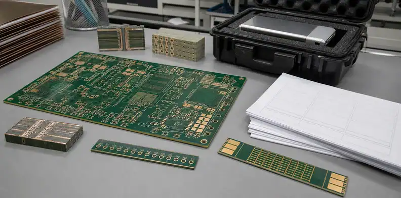
For a board-specific PCB manufacturer capability check, send the 12-input summary plus the controlled Gerber/ODB++ package, drawing, stack-up, impedance table, quantities, and destination through the free PCB DFM review. Ask for a written disposition rather than an informal yes.
Once the technical issues are closed, submit the same revision for quotation through the QueenEMS contact page. The quotation should identify the construction, assumptions, included evidence, exclusions, validity, and change triggers.
FAQ
Is a PCB capability table enough to approve a manufacturer?
No. It is a screening aid. Approval requires a board-specific review of the complete construction, plus separate checks for quality systems, evidence, capacity, commercial scope, and a qualification build when appropriate.
Can a manufacturer build an 8-layer PCB with 3/3 mil spacing?
It depends on copper, stack-up, feature length, holes, registration, impedance, panel, and the supplier’s controlled process. Ask for a CAM review and a written disposition of the complete combination.
What can I send before sharing full Gerber files?
Send sanitized layer count, dimensions, thickness, copper, minimum trace/space, holes, via structures, material, impedance, finish, special processes, quantities, and product stage. Treat the answer as provisional until controlled data is reviewed.
Does the smallest drill size equal the finished hole size?
No. The drill tool and finished plated hole are different values because plating and process tolerances affect the final diameter. Specify the finished requirement and let the fabricator confirm the production route.
Should a manufacturer be allowed to adjust trace width?
Only under a defined approval rule. Controlled-impedance fabrication may require geometry adjustment, but the supplier should return the proposed value and obtain the required design approval before release.
Sources
- Ucamco Gerber Job File overview: https://www.ucamco.com/en/gerber/gerber-job-file
- IPC-2581C table of contents and scope: https://www.ipc.org/TOC/IPC-2581C-toc.pdf
- IPC-6012 rigid printed board specification overview: https://shop.electronics.org/ipc-6012/ipc-6012-standard-only/Revision-d/english
- IPC document revision table: https://www.electronics.org/ipc-document-revision-table
Written by the QueenEMS Engineering Team
Upload your files today · Free DFM check before production · Ship worldwide
Get your PCB prototypes in as fast as 24 hours. We handle FR4, Rogers, and Flex up to 60 layers — free prototypes for 2–4 layer boards, no minimum order.
Just upload your Gerber + BOM — we source every part, assemble, and inspect (AOI + X‑Ray) so you don't have to chase suppliers. Boards ship in as fast as 24 hours.