
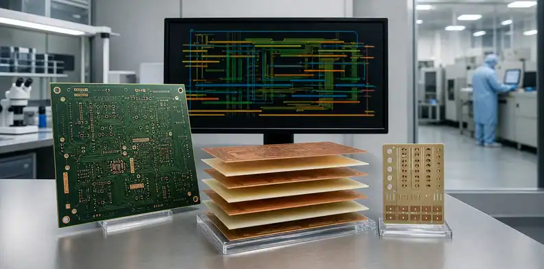
Quick Answer: The minimum PCB fabrication quote files are usually Gerber layer data, NC drill data, a fabrication drawing or requirements sheet, quantity, and delivery destination. A production-ready package should also control the revision, stack-up, material, copper, thickness, finish, tolerances, impedance, special processes, electrical test, quality records, and quote assumptions; use the 10-part checklist below before accepting a price.
Key takeaways – Gerber and drill files describe geometry, but they may not carry every fabrication requirement. – ODB++ or IPC-2581 can consolidate intelligent data when both buyer and supplier support the exchange. – Separate fixed requirements from supplier-proposed stack-up or material options. – Keep BOM, CPL, assembly drawings, and functional test out of a bare-board-only RFQ.
A bare PCB quote can look precise even when the supplier has silently assumed a standard material, thickness, finish, stack-up, test scope, and delivery term. Those defaults may be acceptable for an early estimate, but they should not become production requirements by accident.
This guide explains what to send for a bare-board quotation, how Gerber, drill, drawing, and intelligent formats work together, and which missing notes commonly cause a requote. If components will also be placed, use the broader PCB assembly RFQ checklist instead.
Table of Contents
- What Makes a Fabrication Quote Production-Ready?
- What Is the Minimum File Package for an Estimate?
- What Must Gerber and Drill Data Include?
- When Should You Send ODB++ or IPC-2581?
- What Belongs in the Fabrication Drawing?
- How Should Stack-Up and Impedance Be Defined?
- How Do Material, Copper, and Finish Affect the Quote?
- Which Mechanical, Test, and Quality Notes Matter?
- How Should You Control Revisions and Requotes?
- What Is the Final Fabrication RFQ Checklist?
What Makes a Fabrication Quote Production-Ready?
A production-ready fabrication quote references one controlled board revision and makes the construction, included processes, tests, records, commercial assumptions, and exclusions visible. It gives purchasing a defined basis for releasing an order.
The quotation should identify:
- customer part number and revision;
- reviewed manufacturing-data archive;
- board quantity and whether pricing is per piece, array, or panel;
- proposed or approved construction and material rule;
- included finish, special processes, tests, coupons, reports, tooling, and NRE;
- lead-time basis and the event that starts the clock;
- quote validity, currency, payment, delivery location, and Incoterm;
- assumptions, options, exclusions, and changes that require a requote.
An early price generated from dimensions, layers, and broad technology can still be useful. Label it as a budgetary estimate. Do not release production until the supplier has reviewed the controlled data and the quote reflects any CAM or stack-up changes.
The phrase “firm quote” is not a universal guarantee. Its practical value comes from a stable revision and explicit assumptions. Material availability, quantity, schedule, design changes, approvals, or expired validity may still require a new review.
Keep this bare-board scope distinct from PCBA. A BOM, component sourcing, pick-and-place file, assembly drawing, programming package, or functional test specification belongs in an assembly-inclusive RFQ, not in the minimum fabrication package.
What Is the Minimum File Package for an Estimate?
For most custom bare boards, begin with layer images or intelligent PCB data, drill information, a requirement summary, quantities, and destination. The supplier needs enough information to recognize the process route and the main cost drivers.
Use this minimum:
| Input | Why it is needed |
|---|---|
| Gerber and NC drill, ODB++, or IPC-2581 data | Defines board geometry, layers, holes, routing, and other encoded features |
| Board part number and revision | Prevents a quote from becoming detached from the design |
| Layer count, dimensions, and finished thickness | Establishes the broad construction and panel basis |
| Copper weights and material requirement | Identifies etching, lamination, sourcing, and performance assumptions |
| Surface finish | Identifies a required fabrication process |
| Minimum features and special technologies | Flags HDI, heavy copper, rigid-flex, RF, cavities, edge plating, or other nonstandard scope |
| Quantities and product stage | Supports panel, tooling, sampling, and price-break assumptions |
| Destination and requested delivery basis | Supports a meaningful logistics basis |
If stack-up, impedance, material, or panelization remains open, state that explicitly and request a supplier proposal. A good estimate should identify which values were assumed.
You may send a sanitized specification for an initial capability screen, but production pricing normally requires the actual controlled geometry. Dimensions and minimum rules alone cannot reveal hole count, routing complexity, copper distribution, tight local features, or special data conditions.
What Must Gerber and Drill Data Include?
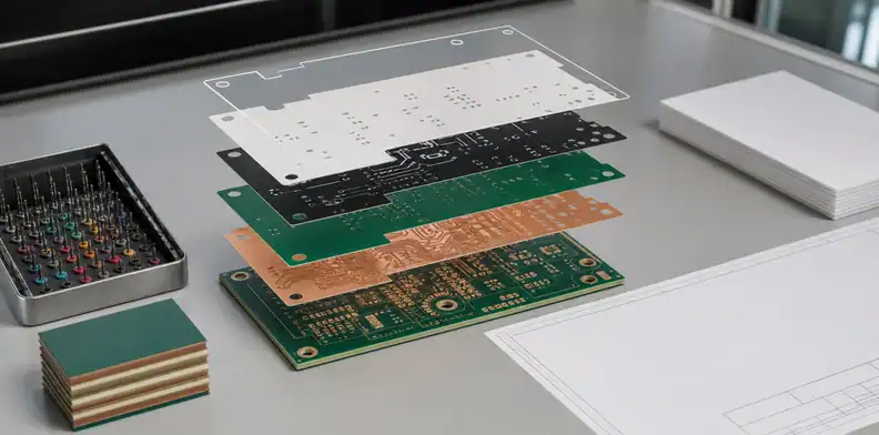
Gerber data should clearly identify every required image layer, while drill data should identify hole locations, tools, plating status, and spans where applicable. Package the files from one CAD release and verify them in an independent viewer before submission.
For a typical rigid board, check for:
- top, bottom, and all internal copper layers;
- top and bottom solder mask;
- top and bottom legend where used;
- board outline and routed features;
- plated and non-plated drill information;
- slots and other mechanical drill/rout features;
- paste layers only when they are relevant to a separate stencil or assembly scope;
- layer names, polarity, units, format, and revision identification.
The exact file extensions vary by CAD system. Do not depend on filenames alone; include a layer map or use format attributes that identify file functions. Check that the outline is closed, no unintended drawings are present on the manufacturing outline, and all drill files align with the copper layers.
Gerber images and drill files may not communicate overall thickness, laminate, stack-up, finish, copper, controlled impedance, tolerances, special plating, acceptance criteria, or shipment records. Ucamco’s Gerber guidance specifically distinguishes layer images from the broader fabrication information needed for quoting and manufacturing.
The Gerber package generation guide covers export and viewer checks in more depth. This page owns the quotation package, not the CAD export procedure.
When Should You Send ODB++ or IPC-2581?
Send ODB++ or IPC-2581 when your design system exports a controlled, validated dataset and the receiving manufacturer supports that version and workflow. Intelligent formats can carry geometry, attributes, net information, stack-up, components, and other manufacturing data in a more structured exchange.
They are useful when:
- the board has many layers, drill spans, net attributes, or complex features;
- the supplier wants a netlist for electrical-test or CAM comparison;
- the buyer and supplier use an agreed digital thread for DFM feedback;
- manual interpretation of separate drawings and text would create avoidable risk;
- assembly information is also exchanged, even though the current quote may remain bare-board only.
Do not assume that an intelligent dataset eliminates the need for a drawing or requirements summary. The supplier may still need customer-controlled notes, performance requirements, tolerances, approved materials, deviations, records, and commercial information. Confirm which dataset controls when there is a conflict.
IPC describes IPC-2581C as an XML-based manufacturing-description exchange that can support fabrication, assembly, inspection, and DFX feedback. Ucamco’s Gerber Job File provides machine-readable fabrication information alongside Gerber data. ODB++ is another established intelligent manufacturing-data approach. The best format is the one both parties can export, review, version, and interpret reliably.
If you provide more than one manufacturing format, label one as controlling and the others as references. Conflicting Gerber, ODB++, and drawing revisions should stop the quotation review.
What Belongs in the Fabrication Drawing?
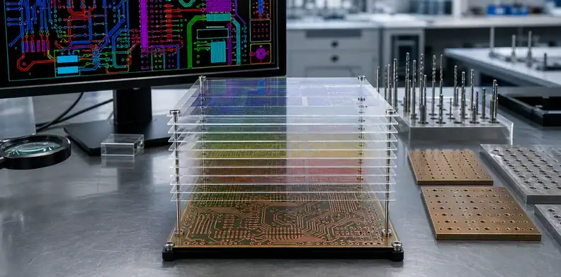
The fabrication drawing should control requirements that are not safely or completely communicated by image and drill data. It should identify the board and revision, not repeat every geometric feature already present in the CAD output.
Include, as applicable:
- finished board dimensions, profile tolerances, and datum scheme;
- finished thickness and tolerance;
- layer count and stack-up reference;
- starting or finished copper requirements;
- laminate designation, performance limits, and substitution authority;
- surface finish and thickness where controlled;
- solder-mask type, color, and special openings;
- legend color and controlled marking requirements;
- drill table, finished-hole notes, plated/non-plated status, slots, and special holes;
- controlled-impedance table and coupon/report requirement;
- edge plating, gold fingers, bevels, castellations, countersinks, cavities, or controlled-depth routing;
- panel, array, scoring, routing-tab, or breakaway requirements when buyer-controlled;
- applicable performance specification, class, deviations, tests, reports, and packaging.
Use notes that can be inspected. A statement such as “high quality required” gives the manufacturer no acceptance criterion. A note such as “no material substitution” is clearer, but it should also identify the controlled material and the approval authority for an exception.
Avoid contradictions between the drawing and data. If the drawing says six layers while the dataset contains eight copper layers, the supplier should stop and request clarification rather than choose one.
How Should Stack-Up and Impedance Be Defined?
Define which stack-up values are fixed, which are electrical targets, and which the supplier may adjust for manufacturability. For controlled-impedance boards, provide target, tolerance, layer, reference plane, trace type, and coupon/report expectations.
Choose one of three control models:
| Model | Buyer controls | Supplier returns |
|---|---|---|
| Buyer-controlled stack-up | Material, dielectric, copper, geometry, and overall construction | DFM confirmation or exception |
| Supplier-proposed stack-up | Electrical/mechanical targets and restricted interfaces | Producible material set, finished dielectrics, geometry, and modeled impedance |
| Hybrid | Critical interfaces plus allowed adjustment ranges | Final proposal and approval items |
State whether trace width or spacing may be adjusted. If yes, define the approval process and how the final value is recorded. Do not let a CAM adjustment exist only in an email when it changes controlled electrical geometry.
Also state whether the quote includes impedance modeling, test coupons, time-domain reflectometry testing, lot-specific reports, or only process control. A phrase such as “controlled impedance included” is incomplete unless the deliverable is clear.
The controlled-impedance PCB guide explains stack-up, geometry, coupons, tolerances, and reports. The PCB trace impedance calculator can support early estimates, but the fabricator’s final model should use the approved production construction.
How Do Material, Copper, and Finish Affect the Quote?
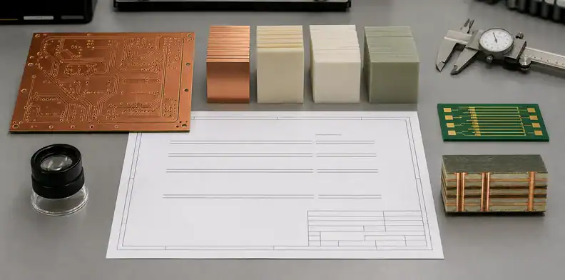
Material, copper, and finish affect both process fit and commercial assumptions. Specify enough detail to prevent an inexpensive default from replacing a required performance characteristic.
For laminate, use one of these approaches:
- exact manufacturer and grade;
- approved list of grades;
- documented limits for supplier-proposed equivalence;
- broad family for a budget estimate, followed by approval before production.
Do not approve an equivalent based on Tg alone. Depending on the application, decomposition behavior, thermal expansion, dielectric properties, loss, thickness availability, copper type, flammability recognition, halogen requirements, CAF performance, assembly profile, or customer qualification may matter.
For copper, distinguish starting foil from finished external copper where necessary. Heavy copper changes etching and spacing capability. Fine features may require a different starting foil or finished geometry. Ask the supplier to state the quoted basis.
For surface finish, identify the type and any controlled thickness, solderability, wire-bonding, connector, shelf-life, or compliance requirement. Selective finishes, gold fingers, hard gold, peelable mask, carbon ink, or edge plating should be called out separately.
If the supplier proposes an alternative material or finish to reduce lead time, request a separate option showing technical, cost, and schedule impact. Approval should occur before fabrication, not after material has been issued.
Which Mechanical, Test, and Quality Notes Matter?
Mechanical, testing, and quality notes matter when they affect equipment, tooling, sampling, records, acceptance, packaging, or responsibility. Put them in the RFQ so the supplier does not price a different release package.
Mechanical items may include:
- tight profile or hole-position tolerances;
- slots, cutouts, internal routing, or controlled depth;
- V-score geometry and residual web;
- countersinks, counterbores, back drilling, or bevels;
- bow/twist or flatness limits;
- panel drawing, tooling holes, rails, coupons, or fiducials;
- marking, serialization, date code, QR code, or lot identification;
- special cleaning, handling, vacuum packaging, desiccant, humidity indicator, or labels.
For bare-board test, state the electrical-test requirement and whether the supplier should use a CAD netlist, extracted netlist, or customer-supplied reference. Identify required impedance, microsection, solderability, ionic cleanliness, material, dimensional, or other records.
Applicable IPC or customer requirements should be referenced by document and revision where needed. Do not describe a supplier as “IPC certified” when the actual requirement is to fabricate and accept the board to a stated performance specification and class.
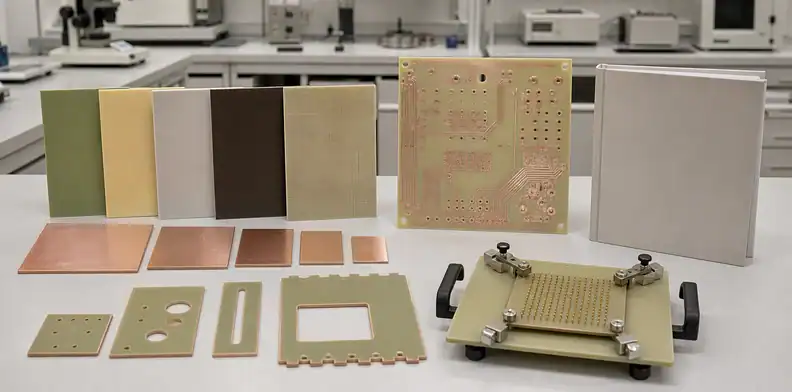
The PCB fabrication certifications guide helps distinguish management-system certificates, product recognition, performance specifications, and shipment evidence.
How Should You Control Revisions and Requotes?
Control the RFQ as a released data package with a unique identity. A clear revision system prevents a supplier from quoting one dataset and building another.
Use:
- project and board name;
- customer part number;
- revision;
- RFQ release date;
- archive filename;
- file manifest;
- optional checksum or controlled-document record;
- named technical and commercial contacts.
Inside the archive, remove superseded outputs and temporary viewer files. Keep Gerber, drill, drawing, stack-up, impedance table, and requirement summary on the same revision. If a reference document has a different revision convention, explain the relationship in the manifest.
These changes commonly require review or requoting:
- board dimensions, layers, thickness, copper, or quantity;
- trace/space, holes, vias, routing, or panel;
- material, finish, controlled impedance, or tolerance;
- added test, coupon, report, marking, or packaging;
- schedule, destination, delivery basis, or partial shipment;
- expired quote validity or changed material availability;
- a new manufacturing-data revision.
Ask the supplier to identify what changed between quotation revisions. A new total without a change log makes it difficult to determine whether price moved because of the design, scope, market conditions, or a corrected assumption.
What Is the Final Fabrication RFQ Checklist?
Run this check before sending the package:
- The board part number, revision, archive, and file manifest agree.
- All copper, mask, legend, outline, drill, slot, and rout data are present and viewer-checked.
- The fabrication drawing defines thickness, copper, material, finish, holes, tolerances, and special processes.
- The stack-up control model and material-substitution rule are explicit.
- Impedance targets, adjustment authority, coupons, testing, and reports are defined.
- Mechanical, panel, marking, packaging, and quality requirements are included.
- Prototype and production quantities are stated separately.
- Destination, delivery basis, requested schedule, validity, and commercial contacts are stated.
- Open items are labeled as supplier proposals, priced options, allowances, or exclusions.
- The quote must reference the reviewed revision and list requote triggers.
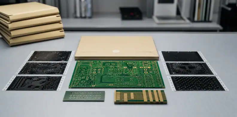
For a completeness review, send the controlled Gerber/ODB++ package, drill files, fabrication drawing, stack-up or impedance table, quantities, material/finish requirements, and destination through the free PCB DFM review. Ask the reviewer to return missing data, conflicts, and proposed changes.
For the production quotation, add the approved quality records, delivery term, and purchasing information, then submit the same revision through the QueenEMS contact page. Require the returned quote to identify construction, tests, reports, assumptions, options, exclusions, validity, and change triggers.
FAQ
Are Gerber and drill files enough for a bare PCB quote?
They can support an estimate for a simple board, but a production quotation also needs construction, material, copper, thickness, finish, tolerances, quantities, tests, quality records, revision, and delivery assumptions.
Do I need a BOM for a PCB fabrication quote?
No. A BOM is normally an assembly input. Include it only when component information affects a clearly defined secondary scope; otherwise keep the bare-board RFQ focused on fabrication.
Should I send ODB++ or IPC-2581 instead of Gerber?
Send an intelligent format when both your design system and manufacturer support a validated workflow. Confirm which dataset controls and retain a drawing or requirements summary for customer-controlled notes.
Do I need a stack-up before requesting a quote?
Not always. You can provide electrical and mechanical targets and ask the supplier to propose a stack-up. The proposal must be reviewed and frozen before production if it affects impedance, material, thickness, or interfaces.
What missing information most often causes a requote?
Quantity, revision, stack-up, material, copper, finish, impedance, holes, special processes, tolerances, tests, reports, panelization, schedule, or delivery changes can all alter the quoted scope.
Sources
- Ucamco Gerber Job File overview: https://www.ucamco.com/en/gerber/gerber-job-file
- Ucamco Gerber downloads and test files: https://www.ucamco.com/en/gerber/downloads
- IPC-2581 Revision C announcement: https://www.ipc.org/news-release/ipc-releases-ipc-2581-revision-c-generic-requirements-printed-board-assembly-products
- IPC-2581C table of contents and scope: https://www.ipc.org/TOC/IPC-2581C-toc.pdf
- IPC document revision table: https://www.electronics.org/ipc-document-revision-table
Written by the QueenEMS Engineering Team
Upload your files today · Free DFM check before production · Ship worldwide
Get your PCB prototypes in as fast as 24 hours. We handle FR4, Rogers, and Flex up to 60 layers — free prototypes for 2–4 layer boards, no minimum order.
Just upload your Gerber + BOM — we source every part, assemble, and inspect (AOI + X‑Ray) so you don't have to chase suppliers. Boards ship in as fast as 24 hours.