
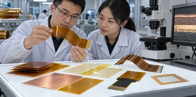
Quick Answer: Flex PCB adhesives must be selected for a specific interface, such as copper-to-film laminate, coverlay, bondply, stiffener, pressure-sensitive mounting, or an electrically conductive connection. Bend mode, reflow history, humidity, chemicals, thickness, peel behavior, cure window, and rework can change the right choice. An adhesiveless flex core removes the adhesive between copper and base film, but the finished circuit may still contain adhesive in its coverlay, stiffener, or mounting system.
Adhesive problems are difficult to diagnose because the bond line is often hidden. A lifted coverlay may appear after reflow, copper may crack beside a stiffener, or a pressure-sensitive mounting layer may creep after the product is installed. Calling all of those failures “bad glue” hides the different materials, interfaces, and process conditions involved.
The correct selection starts by naming what is being bonded. It then connects that interface to static or dynamic bending, assembly heat, field temperature, moisture, chemicals, electrical function, and repair strategy. The material data and the fabricator’s lamination window must describe the same construction.
Table of Contents
- First identify the bonding interface
- Adhesive-based and adhesiveless cores differ
- Acrylic and epoxy serve different stress profiles
- Static and dynamic flex need different decisions
- Reflow history sets a thermal requirement
- Humidity and chemicals attack the interface
- Stiffeners and PSA require local specifications
- Lamination control determines bond quality
- Validate peel, bend, and aging together
- Put the adhesive decision in the RFQ
First identify the bonding interface
The search phrase “flex pcb adhesives” can refer to several layers with different jobs, so the interface must be named before chemistry is compared. A material that works under a stiffener is not automatically suitable inside a dynamic bend or as a pressure-sensitive attachment to a housing.
Core, coverlay, stiffener, and mounting bonds
| Bonding location | What it joins | Main decision drivers |
|---|---|---|
| Adhesive-based flex core | Copper foil to base film | Thickness, bend mode, thermal and dimensional behavior |
| Coverlay adhesive | Coverlay film to patterned circuit | Copper relief, pad openings, flow, reflow, environment |
| Bondply | Flex layers or construction elements | Lamination fill, dielectric thickness, registration |
| Stiffener adhesive | FR-4, polyimide, metal, or other support to flex | Placement, edge stress, heat, connector fit |
| Pressure-sensitive adhesive (PSA) | Finished flex to housing or another surface | Surface energy, pressure, aging, service temperature |
| Anisotropic conductive adhesive | Fine-pitch electrical and mechanical interface | Conductive direction, pitch, pressure, cure, repair |
The same circuit can contain several of these systems. A statement such as “use acrylic adhesive” is incomplete unless it identifies the bond, thickness, material supplier, cure or lamination condition, and application requirement. The flexible PCB manufacturing page is the correct commercial context for the full construction; the article here isolates the bonding decision.
Start the RFQ with a cross-sectional stack-up and local detail drawings. Mark the dynamic bend, static folds, stiffener edges, connector interface, exposed adhesive, mounting area, and any region that must survive reflow. That drawing is more useful than a generic adhesive name because it shows where strain and process heat meet the bond line.
Adhesive-based and adhesiveless cores differ
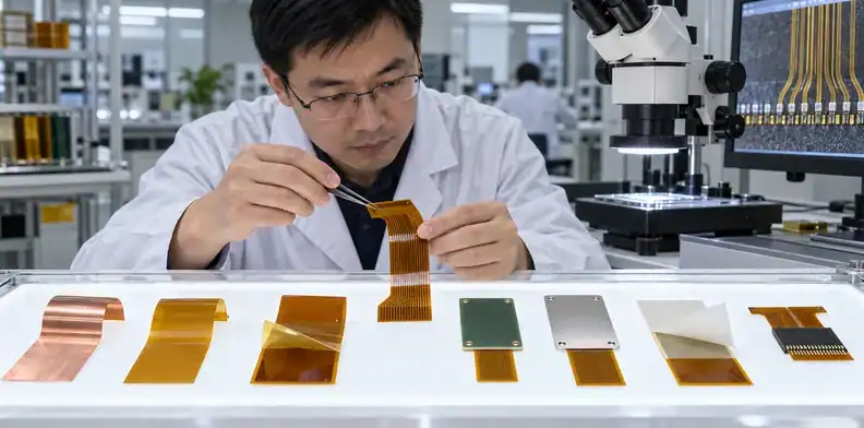
An adhesive-based core uses a separate bonding layer between copper and the flexible dielectric, while an adhesiveless core bonds copper without that discrete layer. Removing the core adhesive can reduce thickness and one mechanical interface, which may help fine geometry, thermal behavior, or repeated flexing.
Adhesiveless does not mean adhesive-free
The completed circuit may still need adhesive-backed coverlay, bondply, stiffeners, or external PSA. Write “adhesiveless copper-clad core” when that is the intended requirement. Writing “no adhesive” can conflict with the physical construction and lead to an impossible quote.
| Decision | Adhesive-based core | Adhesiveless core |
|---|---|---|
| Copper-to-film interface | Separate adhesive layer | No discrete core adhesive layer |
| Thickness contribution | Includes bond-layer thickness | Can support a thinner core construction |
| Dynamic bend | Must evaluate interface strain and material system | Often considered where bend margin is tight |
| Material availability | May offer familiar, economical constructions | Can carry different cost or supply constraints |
| Other adhesives | Coverlay/stiffener/PSA may still be present | Coverlay/stiffener/PSA may still be present |
DuPont’s Pyralux AP data describes a double-sided copper-clad, all-polyimide, adhesiveless laminate intended for flexible and rigid-flex constructions. That product description supports the architectural distinction, but it does not select a thickness, copper type, or complete flex stack-up for every application.
Use the actual supplier datasheet and fabrication capability for approval. Material-family names can include many copper weights, dielectric thicknesses, treatments, and product revisions. A substitution should preserve the properties that matter to bend, electrical, thermal, chemical, and lamination performance. Compare those choices with the broader rigid-flex versus flexible PCB cost factors before treating a thinner core as an isolated material upgrade.
Acrylic and epoxy serve different stress profiles
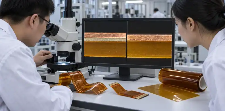
Acrylic and epoxy systems can both produce useful bonds, but their flexibility, modulus, chemical resistance, thermal behavior, cure, flow, and rework differ by formulation. The family name is a screening input, not a complete specification.
Competitor articles often state that acrylic is flexible and epoxy is stiff. That directional comparison can help, but it becomes unsafe when treated as a fixed property. Modified epoxies and acrylic systems cover wide ranges, and the finished bond depends on thickness, cure, adherend preparation, geometry, temperature, humidity, and aging.
For dynamic bending, compare modulus, thickness, fatigue evidence, and bond-edge geometry. High-temperature exposure adds cure state, creep, and retained properties. Chemical contact must name the agent, duration, temperature, and exposed edge. A stiffener bond needs shear or peel behavior tied to local stress transfer, while any rework plan must define the heat or solvent route and its damage boundary.
Pressure-sensitive adhesives belong to another selection path. A PSA is activated mainly by applied pressure and surface contact, making it useful for mounting the finished circuit. It needs clean surfaces, appropriate pressure, dwell, and compatibility with the housing material. It should not be assumed to survive a soldering process merely because another adhesive in the flex stack-up does.
3M’s 467MP product information, for example, identifies a high-performance acrylic transfer adhesive and provides product-specific resistance and application data. Use such data only for that exact product and test condition; it does not establish a general limit for all acrylic PSAs or approve the flex assembly.
Static and dynamic flex need different decisions
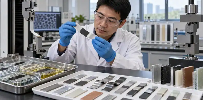
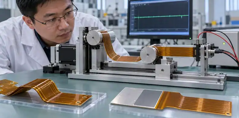
A static flex is formed for installation and then moves little, while a dynamic flex experiences repeated motion during service. The adhesive, copper, stack-up, bend radius, bend direction, length, and transition design must match the actual motion.
Keep stiff bond edges out of the bend zone
A stiffener, coverlay transition, PSA edge, or sudden thickness change concentrates strain. Moving that boundary away from the active bend can matter more than choosing a stronger adhesive. Rounded or tapered transitions, balanced material, suitable copper orientation, and controlled bend geometry help distribute strain.
The flex PCB stiffener requirements are especially relevant at zero-insertion-force (ZIF) connectors, solder interfaces, or supported component regions. The stiffener must achieve the required local thickness and location without putting its bond edge inside repeated motion.
Define minimum installed bend radius and dynamic bend radius separately. State the neutral-axis intent, number of cycles, direction of motion, bend length, fold sequence, and whether the circuit moves while powered. A bend coupon that does not reproduce the production stack or termination may overstate the design margin.
For rigid-flex, control where flex adhesives and no-flow or low-flow prepreg end. The rigid-flex no-flow prepreg review addresses resin flow at the rigid-flex boundary. It complements adhesive selection but should not be collapsed into the same material decision.
Reflow history sets a thermal requirement
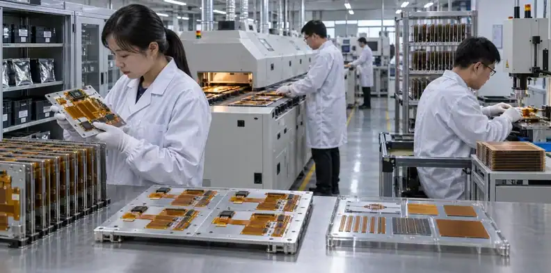
The adhesive system must survive the complete assembly thermal history, not only one published peak temperature. Moisture condition, ramp, time above temperature, number of cycles, fixtures, local copper mass, rework, and post-assembly service can all affect the bond.
Start with the assembly route: solder-paste print, placement, first reflow, second-side reflow if used, selective soldering or hand operations, cleaning, rework, and any later overmolding or bonding. A flex circuit attached with external PSA after soldering has a different requirement from one that enters reflow with the PSA already present.
Record the number of heat cycles in the assembly traveler and include the rework allowance. Document storage, bake, and floor-life rules where moisture conditioning matters. If a carrier is used, identify its material and support drawing. State when each PSA or stiffener is applied so a later-stage bond is not exposed unnecessarily. Finally, keep the service mission profile separate: surviving assembly heat does not prove field life.
Ask for the property that matters after the exposure: peel retention, dimensional stability, absence of blistering, connector position, electrical continuity, or visual acceptance. A material can stay attached after reflow and still move enough to violate a fine-pitch connector dimension.
The PCB assembly process overview can help map the heat stages, but flex-specific carriers, stiffeners, and bonding operations still need their own traveler and acceptance criteria.
Humidity and chemicals attack the interface
Environmental selection must examine the bonded construction, exposed edges, residues, and mechanical load under the named moisture or chemical condition. A datasheet value measured on another substrate or at another thickness may not predict the finished flex circuit.
Test the full bonded construction
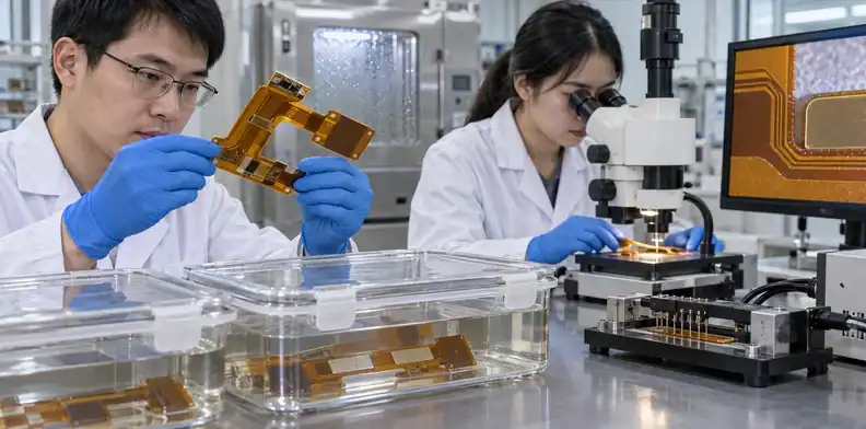
List the actual agents: water, condensation, sweat, skin oils, cleaning fluid, coolant, fuel, lubricant, disinfectant, solvent, salt, or process chemistry. State concentration, temperature, duration, pressure, whether the bond edge is exposed, and whether the circuit is strained or electrically biased.
Moisture can change adhesion, dielectric behavior, corrosion risk, and dimensional stability. Residues left before lamination or mounting can reduce wetting and create local weak areas. Surface preparation, storage, handling, and delay between cleaning and bonding therefore belong in the process definition.
An environmental pass should not be visual only. Depending on the interface, measure peel or shear retention, insulation resistance, dimensional movement, continuity during flexing, appearance, and connector fit. If coating or enclosure protects the assembly, test the representative protection rather than an exposed coupon that the product will never use.
The PCB ionic-cleanliness evidence guide is useful when assembly residues and bias-related risk are involved. It does not replace bond preparation controls or chemical-compatibility testing for the adhesive itself.
Stiffeners and PSA require local specifications
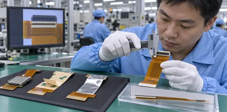
Local bonds should be dimensioned and inspected as functional features because their position and edge condition can control connector fit, component support, and strain. A material callout without location tolerance is not enough.
Placement tolerance can matter as much as chemistry
At a ZIF connector, stiffener thickness, setback, edge position, planarity, and alignment with exposed contacts affect insertion and retention. At a component area, the stiffener may support solder joints but create a fatigue point if its edge crosses a moving zone. A metal stiffener may also change heat spreading or grounding behavior.
For PSA mounting, define the bonded surface, adhesive outline, liners, application side, pull tab, excluded areas, orientation, pressure, dwell, and delivery condition. The assembly plant needs to know whether the liner stays on during shipment and which surface must remain clean.
For a connector stiffener, dimension material, thickness, setback, edge, and placement tolerance, then measure position and finished thickness. A component stiffener needs an outline, bond area, and no-bend region plus an assembly-fit check. Housing PSA drawings should show the exact cut, liner, exposed side, keep-outs, and alignment method. Shield foil needs overlap, grounding intent, edge sealing, and continuity evidence. A heat-spreading attachment also needs interface area, application pressure, and thermal verification.
Do not place links, markings, or cosmetic requirements in a way that hides the adhesive edge from inspection. If the bond is safety- or function-critical, define an acceptance sample, peel tab, coupon, or process audit that can verify it without destroying every part.
Lamination control determines bond quality
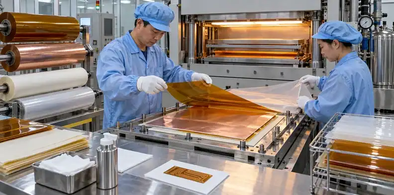
A suitable adhesive can fail when surface preparation, storage, lamination pressure, temperature, vacuum, time, tooling, or cure falls outside its process window. Material selection and manufacturing capability must be approved together.
The bond line must wet the intended surfaces without starving, trapping voids, flowing into openings, moving the stack, or leaving excess squeeze-out. Heavy copper, deep relief, large coverlay openings, and mixed local thickness can change pressure distribution and adhesive fill.
| Process variable | Failure it can influence | Evidence to request when critical |
|---|---|---|
| Material storage and conditioning | Moisture, contamination, early reaction | Lot and handling record |
| Surface preparation | Low adhesion or local lift | Controlled cleaning/preparation method |
| Lamination heat and time | Under-cure, over-flow, material damage | Qualified recipe and traveler |
| Pressure and vacuum | Voids, poor fill, registration movement | Process control and coupon/result |
| Tooling and release materials | Imprint, contamination, nonuniform pressure | Approved tooling construction |
Coverlay openings deserve particular attention because adhesive can squeeze into pads or retreat from copper edges. The local copper relief, adhesive thickness, opening geometry, registration capability, and lamination flow must work as one design. A separate solder-mask opening article cannot be used as the rule for flex coverlay because the materials and process differ.
Before volume production, agree on what a void, lift, squeeze-out, stain, or edge condition looks like under the selected inspection method. A photo sample can support workmanship communication, but measurable drawing and acceptance criteria remain the governing record.
Validate peel, bend, and aging together
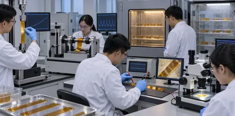
Initial peel strength cannot predict dynamic flex life, thermal cycling, humidity aging, or performance beside a stiff transition. Validation should reproduce the production construction and the combined stresses that matter to the product.
An illustrative delamination investigation
Imagine a flex tail that passes incoming visual inspection but lifts beside a stiffener after two assembly heat cycles and repeated connector insertion. The correct investigation would preserve samples, identify the failure interface, compare material lots, review surface preparation and cure, measure stiffener position, inspect the bond edge, and reproduce the thermal and mechanical sequence. Changing to a “stronger” adhesive before locating the interface could move the failure into the copper trace.
The corrective action might involve surface preparation, cure, adhesive thickness, stiffener setback, bend restriction, or a different bonded construction. Verification should repeat the production thermal sequence, connector insertion, and representative flexing, then inspect continuity, bond condition, and fit. This is an illustrative engineering scenario, not a claimed QueenEMS customer event, and it does not promise that one change solves every lift.
| Validation method | What it can reveal | Limitation |
|---|---|---|
| Peel or shear test | Comparative bond strength under stated geometry | May not reproduce dynamic strain |
| Dynamic bend test | Circuit and interface fatigue in motion | Fixture must match bend length and direction |
| Thermal cycling | CTE and interface stress over cycles | Needs relevant temperature profile and dwell |
| Humidity/chemical aging | Property retention under exposure | Must use the named agent and full construction |
| Assembly trial | Movement, blistering, fit after process heat | Does not prove long-term field life alone |
IPC-6013 covers qualification and performance requirements for flexible printed boards designed to the related IPC design standards. State the applicable revision, class or type, and product exceptions; the number alone does not select an adhesive or define the bend test.
Put the adhesive decision in the RFQ
A quote-ready flex package identifies every bond, its materials, geometry, process exposure, service condition, inspection, and change-control boundary. This lets engineering evaluate a construction instead of guessing from the word “flex.”
| RFQ input | What to send | What the supplier should return |
|---|---|---|
| Cross-sectional stack-up | Copper, dielectric, adhesive, coverlay, bondply | Supported material set and thickness |
| Local bond drawings | Stiffener/PSA outlines, setback, tolerances, liners | Placement capability and inspection method |
| Bend definition | Static/dynamic, radius, length, direction, cycles | Construction and test recommendation |
| Thermal history | Reflow cycles, rework, service profile | Compatibility, conditioning, process limits |
| Environment | Humidity and named chemicals with duration | Compatibility gaps and validation plan |
| Change control | Locked products and allowed property ranges | Substitution notice and approval evidence |
Use one controlled revision for Gerber or ODB++, drill, outline, stack-up, stiffener drawing, PSA drawing, assembly profile, and mechanical model. If the supplier proposes an alternate adhesive, require the exact product or construction, reason, affected dimensions, supporting data, and validation impact.
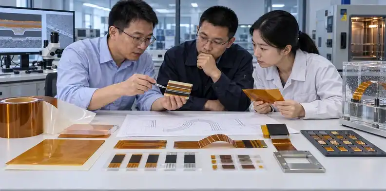
For a construction review and quotation, send QueenEMS the flex stack-up, bend map, stiffener and PSA details, assembly heat history, chemical/moisture exposure, connector drawing, validation plan, and prototype/production quantities. The return can define the supported bonding route, open DFM questions, material approval boundary, and test evidence needed before release.
FAQ
Does an adhesiveless flex PCB contain no adhesive at all?
No. The term usually refers to the copper-to-base-film core. The circuit may still use adhesive in coverlay, bondply, stiffeners, or pressure-sensitive mounting layers.
Is acrylic always better than epoxy for bending?
No. Formulation, thickness, cure, geometry, temperature, and environment matter. Compare product-specific data and test the finished construction under the intended bend condition.
Can pressure-sensitive adhesive go through reflow?
Only when the exact PSA product and application sequence are qualified for that exposure. Many mounting PSAs are better applied after high-temperature assembly.
What should be tested for a dynamic flex circuit?
Test the production stack-up, bend radius and length, motion direction, cycle requirement, terminations, thermal history, and environment while monitoring electrical continuity and bond condition.
Does higher peel strength guarantee longer flex life?
No. Peel strength measures one loading geometry. Dynamic life also depends on copper, dielectric, adhesive modulus and thickness, bond edges, bend geometry, termination, temperature, and aging.
Sources
- IPC-6013: Qualification and Performance Specification for Flexible Printed Boards
- Qnity Pyralux AP Adhesiveless Laminate Data Sheet
Written by the QueenEMS Engineering Team
Upload your files today · Free DFM check before production · Ship worldwide
Get your PCB prototypes in as fast as 24 hours. We handle FR4, Rogers, and hybrid boards up to 40 layers in volume production, with advanced builds subject to engineering review — free prototypes for 2–4 layer FR-4 boards, no minimum order.
Just upload your Gerber + BOM — we source every part, assemble, and inspect (AOI + X‑Ray) so you don't have to chase suppliers. Boards ship in as fast as 24 hours.