
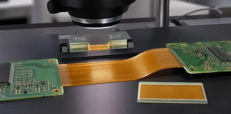
Quick Answer: Rigid-flex no-flow prepreg must bond the rigid sections without flooding resin into the active flex area or leaving dry, weak interfaces near the transition. Freeze the prepreg grade, cutout geometry, resin-flow acceptance, lamination sequence, flex-zone protection and inspection evidence before quotation. “Use no-flow” is incomplete because material condition, artwork density, pressure distribution and window design determine the actual bond line.
Rigid-flex lamination asks one bonding material to do two apparently conflicting jobs. It must flow enough to wet and consolidate the rigid construction, yet remain controlled at the edge of the flexible region. A poor balance creates resin squeeze-out, unsupported corners, voids, local thickness change, stiffened bends or delamination.
This process deserves its own article because it is not a bend-radius calculation or coverlay-opening decision. Those design topics interact with lamination, but no-flow prepreg selection and press control require a separate release package.
Table of Contents
- Define the job of the no-flow bonding layer
- Freeze material identity and incoming condition
- Design prepreg windows and transition geometry
- Control lay-up pressure, heat and resin movement
- Inspect squeeze-out, voids and bond-line quality
- Connect lamination to thickness and registration
- Qualify changes before repeat production
- Send a quote-ready rigid-flex lamination package
Define the job of the no-flow bonding layer
Material rule: No-flow means restricted and qualified resin movement for a defined construction, not a promise that the prepreg remains dimensionally inert during cure.
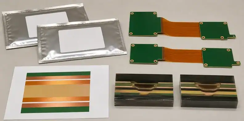
No-flow and low-flow prepregs are formulated to limit resin movement compared with conventional high-flow rigid-board prepreg. In rigid-flex construction, they bond rigid cores or cover layers to a flex core while helping keep resin out of the exposed flex window. “No-flow” does not mean zero movement under every press condition.
The material still must fill intended copper topography and create a continuous bond. If flow is too restricted for the local copper pattern, glass style, thickness or pressure distribution, the panel can retain voids or resin-starved areas. If flow exceeds the transition allowance, cured resin can extend into the flex region, alter bending behavior or contaminate pads.
Define the functional zones first:
- rigid component islands that require full structural consolidation;
- rigid-to-flex transitions that need a controlled bond edge;
- active static or dynamic flex areas that must remain free;
- connector or stiffener areas with local thickness requirements;
- plated-hole regions that cross mixed materials;
- coverlay and copper features near the lamination window.
The rigid-flex versus flexible PCB cost comparison helps choose the architecture. Once rigid-flex is selected, the no-flow process must be designed around the exact zones and failure consequences.
Write acceptance in terms of bond, squeeze-out, voids, transition condition and finished thickness. Allow the supplier to propose qualified press settings and tooling that achieve those outputs.
Freeze material identity and incoming condition
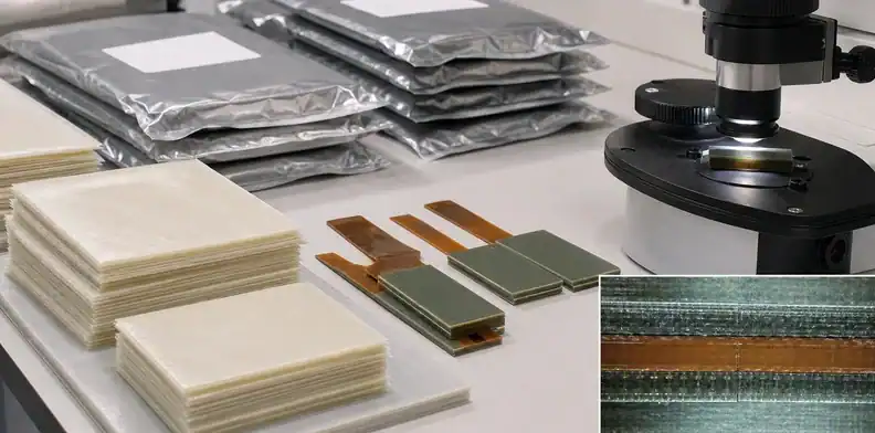
No-flow products are not generic substitutes for one another. Resin chemistry, glass style, resin content, cured thickness, flow test, storage life and lamination guidance vary by product and revision. A supplier’s experience with one material does not automatically qualify another.
The stack-up and purchase specification should identify manufacturer, grade, glass style or construction, nominal cured thickness and applicable material specification. Record whether the product is true no-flow, low-flow or another controlled-flow bonding material. Those terms can be used loosely in commercial discussions, so the datasheet and supplier proposal must resolve the actual choice.
Incoming handling affects repeatability. The fabricator should control refrigerated or dry storage where required, exposure time, conditioning, lot traceability and material age according to current manufacturer guidance. The buyer does not need warehouse logs with every quotation, but should require confirmation that expired or improperly conditioned material will not be used.
First-article evidence should name the material lot and relate it to the lamination run. If flow behavior changes, traceability helps distinguish an artwork or tooling issue from a prepreg condition problem.
Incoming acceptance should also connect to the manufacturer’s stated flow test or processing method. A flow value measured by one test configuration should not be compared directly with a different method as though the numbers were interchangeable. The supplier should use the method specified for the selected product and maintain its own qualified relationship between incoming data and finished bond quality.
A material substitution request must include more than dielectric constant and Tg. Compare flow characterization, cured thickness, resin system, adhesion to the flex and rigid materials, thermal behavior, storage rules and qualified press cycle. The approved replacement should become a named revision, not an informal purchasing alternative.
Design prepreg windows and transition geometry
Geometry rule: Window compensation, coverlay overlap, copper topography, and flex keepouts must be reviewed together before the lamination tooling is released.
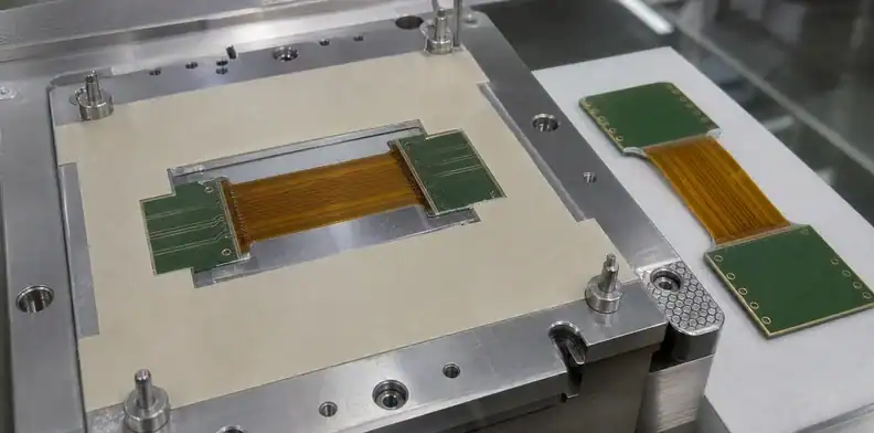
The prepreg is commonly pre-routed or otherwise opened over the flex region before final lamination. Window size, corner radius, edge position and alignment determine where resin can end and how pressure is transferred at the rigid-to-flex boundary.
Define window geometry from controlled board datums. The prepreg opening, rigid-layer opening, coverlay edge and flex copper keepout should not be separate drawings with unrelated origins. Misregistration among them can expose unsupported adhesive, trap a ridge under the flex, or move cured resin into a bend.
Transition features need room for cumulative tolerance. Include prepreg cutting, lay-up alignment, material movement, rigid-layer registration and final flex-area opening. A nominal line with no tolerance invites each supplier to make a different assumption.
Avoid forcing the no-flow article to own every flex design rule. Use the planned flex drawing to define coverlay and bend relationships, while this lamination package controls the bonding edge. The existing flex PCB stiffener requirements remain the owner for connector support and ZIF thickness.
Ask how the supplier handles narrow rigid webs, acute inside corners and closely spaced windows. Pressure and resin behavior can differ from a broad straight transition. When a transition is critical, include a dimensioned detail and identify the surface that will be inspected after cover removal.
Control lay-up pressure, heat and resin movement
Lamination combines temperature, pressure, vacuum, dwell and cooling into one consolidation cycle. Material supplier guidance provides a starting envelope, but panel construction, copper distribution, tooling and press loading determine the local result.
The supplier should show that the proposed cycle is qualified for the prepreg and flex materials. Relevant process controls include:
- lay-up sequence and orientation;
- release films, separator plates and local pressure tooling;
- vacuum or evacuation before resin gel;
- pressure application relative to resin viscosity;
- cure temperature and time appropriate to the material;
- controlled cooling that limits residual stress;
- panel placement and load consistency.
Pressure tooling deserves a separate review near multiple flex windows or irregular rigid islands. A uniform press load does not guarantee uniform local pressure when large openings remove support from selected zones. Caul plates, compliant materials, release films and local fillers can redistribute load, but they can also mark the panel or change thickness if applied inconsistently. Require the supplier to identify the tooling family used for the approved construction and to treat a substantial tooling change as a process review item.
Heavy copper and open laminate areas do not present the same fill demand. A coupon with uniform copper may not represent a rigid island containing dense planes beside a large clearance. Review resin demand and pressure distribution against real artwork.
The hybrid PCB lamination evidence gives the broader framework for mixed-material CTE and delamination risk. Here the evidence should focus on the no-flow bond line and the flex transition rather than repeating the entire hybrid stack review.
Do not specify a copied press recipe as a universal requirement. Ask for the finished evidence, approved process family and notification when a change to material, tooling or press route could affect the bond.
Inspect squeeze-out, voids and bond-line quality
Acceptance check: Surface appearance alone is insufficient when the controlled feature is a hidden bond line or resin condition at the rigid-flex transition.
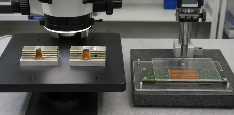
Visual inspection can reveal resin extending into the exposed flex area, contamination on contacts, an irregular transition edge or damage from cover removal. It cannot show every hidden void or starved bond. Pair surface inspection with representative sections through the transition and rigid bond area.
Define the observation and its limit:
| Condition | Inspection view | Acceptance question |
|---|---|---|
| Resin squeeze-out into flex | Surface view after opening | Does cured resin enter a controlled bend, pad or keepout zone? |
| Dry or starved bond | Cross-section through rigid area | Is dielectric support continuous around copper topography? |
| Void near transition | Section or validated non-destructive method | Does it reduce bond area or create a crack path? |
| Bond-line thickness variation | Measured section | Does it alter total thickness, impedance or mechanical fit? |
| Flex or coverlay damage | Surface and section | Did tooling or cover removal nick the flexible construction? |
| Edge delamination | Magnified transition view | Is separation present before assembly stress? |
State whether small resin fillets are permitted and where they are measured. A blanket “no adhesive squeeze-out” note may be unrealistic; an unlimited visual allowance is equally unhelpful. Tie the limit to flex function, pad clearance and drawing geometry.
Choose section locations before the lot is built. Include the narrowest rigid web, the highest copper step, the most critical bend transition and another representative area when construction varies. Record layer names, material, lot, orientation and measured bond-line values.
Connect lamination to thickness and registration
No-flow prepreg contributes to local dielectric and total board thickness. Variability can affect controlled impedance in the rigid zone, component seating, stiffener relationship, plated-hole aspect ratio and the mechanical transition into flex.
Use a zone-based stack-up that shows which layers continue through flex and which exist only in rigid areas. The broader PCB stack-up design workflow can organize materials and layer functions, while this rigid-flex record must also state nominal cured thicknesses and finished zone thicknesses. If an impedance line crosses or approaches the transition, identify the reference-plane and dielectric changes rather than applying one line-width rule across unlike zones.
Registration also spans different materials. Polyimide and rigid laminates can move differently during imaging and lamination. The prepreg window must align with the flex core, rigid layers, coverlay and later routed opening. Ask how the supplier measures movement and compensates tooling without moving functional copper.
Global flatness can be affected by asymmetric layer count, copper distribution and material placement. Apply the PCB bow and twist acceptance to the finished panel while separately inspecting the local transition.
When the no-flow bond changes an impedance or thickness assumption, update the controlled stack-up and drawing before release. Do not leave the accepted value in an email while the fabrication data still shows the earlier construction.
Qualify changes before repeat production
Change signal: A different prepreg grade, window design, press family, or cover-removal route requires evidence that the approved transition remains representative.
The first successful lot establishes a process baseline, not permission for silent substitutions. Record the prepreg grade and lot family, flex laminate, rigid material, stack-up revision, window geometry, lay-up method, press route, inspection plan and accepted evidence.
Review changes that can alter resin movement or bond quality:
- prepreg manufacturer, grade, glass style or resin content;
- flex core or coverlay construction;
- copper weight or major copper-density change;
- window size, corner geometry or tooling method;
- press equipment or external lamination source;
- panel size, array layout or rigid-island arrangement;
- cure cycle outside the qualified family;
- added sequential lamination.
Not every maintenance action requires customer approval. Define a threshold based on process identity and product effect. A new press with an equivalent qualified recipe may need supplier requalification evidence; a change to the approved material or transition geometry needs engineering review and a revised release record.
If a lot shows squeeze-out or voids, contain panels by lamination load, material lot and tooling setup. A cosmetic rework at the flex opening cannot restore a hidden weak bond. Require a disposition that addresses the observed mechanism and verifies the corrected process.
Cover removal is another controlled step. External rigid material above the flexible zone may be routed before lamination and retained as a temporary cover until final processing. The method used to release that cover must avoid cutting the flex, peeling coverlay, leaving a resin ridge or applying excessive bending force. Add the cover-removal tool and inspection point to the baseline when the construction uses this route.
Record lessons from the engineering lot in dimensions and evidence, not in informal operator memory. If the accepted build needed a larger window allowance, different pressure support or a revised material lay-up, update the released supplier drawing and repeat-order package before closing the lot.
| Proposed change | Minimum requalification question |
|---|---|
| Prepreg grade | Does flow, cured thickness, adhesion, and storage behavior remain representative? |
| Window geometry | Does the transition still meet squeeze-out, fill, and flex-keepout limits? |
| Press or tooling family | Do bond-line measurements and local registration remain within the baseline? |
| Cover-removal route | Can the flexible construction be exposed without cuts, peel, or a resin ridge? |
Send a quote-ready rigid-flex lamination package
The RFQ should include intelligent fabrication data or complete Gerbers, separate rigid and flex outlines, stack-up by zone, exact material callouts, prepreg windows, coverlay layers, copper weights, drill data, controlled impedance, finished thicknesses, flex function and inspection class.
| Lamination record | Required definition |
|---|---|
| Material identity | No-flow grade, resin state, cured thickness and approved substitute rule |
| Transition geometry | Prepreg window, coverlay overlap, copper keepout and rigid-edge datum |
| Process family | Lay-up, tooling, pressure support, cure control and cover-removal route |
| Evidence | Surface view, transition section, bond-line measurement and lot identity |
Ask suppliers to return:
- proposed no-flow or low-flow prepreg identity;
- qualified cured thickness and material revision;
- window compensation and transition assumptions;
- lay-up and lamination process family;
- areas where resin fillet or squeeze-out is expected;
- section locations and reported bond-line measurements;
- first-article and repeat-lot evidence;
- material and process change-notification rules;
- price and lead-time effects of special tooling or lamination cycles.
Compare the construction, not just the rigid-flex layer count. One quote may assume an established no-flow build and transition sections; another may leave the window geometry and evidence to post-order engineering. Those offers carry different risk.
A QueenEMS quotation review starts with the zone stack-up, material datasheets, prepreg and rigid-layer windows, coverlay, copper distribution, controlled bend zones, thickness requirements, evidence plan, and quantity. Upload that package through the contact page so the approved response can become a repeatable fabrication baseline.
FAQ
Does no-flow prepreg have zero resin movement?
No. It is designed for restricted flow, but actual movement depends on material condition, copper topography, pressure, temperature, tooling and the construction being laminated.
Can standard FR-4 prepreg be used beside a flex window?
Only when a qualified construction controls resin movement and meets the flex-zone acceptance. Standard high-flow material can intrude into the flex area, so the supplier must justify and verify the proposed route.
How is prepreg squeeze-out inspected?
Use a controlled surface view after the flex area is opened and representative cross-sections through the transition. Define the datum, allowed fillet or keepout, bond-line measurements and lot identity.
Can the supplier substitute another no-flow grade?
Only after comparing flow behavior, cured thickness, adhesion, storage, thermal properties and the qualified press process. Record the accepted substitute in a named revision.
Sources
- Isola Group, FR406N No-Flo and FR406 Lo-Flo Processing Guide
- IPC, Board design standards including IPC-2223
Written by the QueenEMS Engineering Team
Upload your files today · Free DFM check before production · Ship worldwide
Get your PCB prototypes in as fast as 24 hours. We handle FR4, Rogers, and hybrid boards up to 40 layers in volume production, with advanced builds subject to engineering review — free prototypes for 2–4 layer FR-4 boards, no minimum order.
Just upload your Gerber + BOM — we source every part, assemble, and inspect (AOI + X‑Ray) so you don't have to chase suppliers. Boards ship in as fast as 24 hours.