
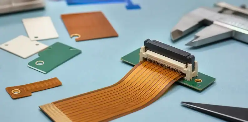
Quick Answer: A flex PCB stiffener should be specified where the flexible circuit needs controlled thickness, connector support, soldering stability, or mechanical handling support. The RFQ should define stiffener material, thickness, location, adhesive, bend keep-out, connector target thickness, and inspection evidence. FR4, polyimide, and stainless steel stiffeners solve different problems, so a buyer should not let the supplier choose silently.
Key takeaways
- ZIF and FFC/FPC connectors usually need a controlled finished tail thickness.
- FR4, polyimide, and steel stiffeners are not interchangeable even if the outline looks similar.
- Put stiffener outline, side, thickness, adhesive, and bend keep-out into the drawing.
- Ask the supplier to confirm the finished stack before assembly or connector testing.
Flex PCB stiffener problems usually appear late: the tail does not fit the ZIF connector, solder joints crack near a rigid area, or the assembly operator bends the circuit at the wrong boundary. The cost is rarely the stiffener itself; the cost is the rework after the buyer thought the flex drawing was already clear. This article focuses on order-ready decisions. It does not try to replace a flex design standard. It shows what purchasing, engineering, and assembly should lock before sending a flexible PCB or flex assembly to quotation.
Table of Contents
- Define the stiffener job before choosing material
- Choose FR4, polyimide, or steel by function
- Lock the ZIF tail thickness and insertion side
- Keep bend zones away from stiffener edges
- Specify adhesive and side, not just outline
- Ask assembly what it needs before quotation
- Write a stiffener RFQ note that can be built twice
Define the stiffener job before choosing material
A stiffener is not only a piece added to make a flex circuit stronger. It may control connector insertion thickness, support SMT parts, spread handling force, protect solder joints, or keep the tail flat during assembly. Each job can lead to a different material and thickness.
Support rule: Name the mechanical job first; material choice follows the connector, soldering, and handling problem.
A buyer can ask the supplier to propose a stiffener only after the drawing identifies the supported zone. If the supplier has to infer the function from Gerbers, it may place the right shape on the wrong side or quote a material that does not match the connector.
For RFQ clarity, separate the flex circuit itself from the stiffener. The flex stackup tells you copper, coverlay, adhesive, and base film. The stiffener note tells you what is added locally and why.
The same stiffener can carry more than one job, but the drawing should still name the primary job. A ZIF tail and an SMT support island may use different thickness targets, and treating them as one generic reinforcement note can create confusion.
Choose FR4, polyimide, or steel by function
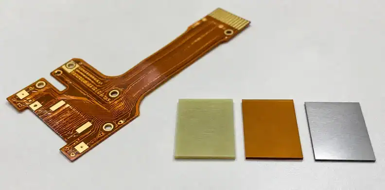
FR4 stiffeners are common for connector support, component areas, and zones that need ordinary PCB-like rigidity. Polyimide stiffeners keep the construction closer to the flex material and can be useful where thinner, lighter, or more compatible reinforcement is needed. Stainless steel can help where rigidity, spring behavior, or thickness control is central, but it changes process and cost.
The wrong choice can pass drawing review and still fail in handling. A stiffener that is too rigid near a bend can concentrate stress. A stiffener that is too soft at a connector tail can create insertion variation.
| Stiffener type | Common use | Buyer risk to control |
|---|---|---|
| FR4 | Connector tail or component support | Finished thickness and side |
| Polyimide | Thin local reinforcement | Adhesive and bend transition |
| Stainless steel | High rigidity or special mechanics | Process, edge, and bonding review |
| No stiffener | Free bend or low handling stress | Connector fit and assembly handling |
If the flex circuit is part of a larger flexible PCB manufacturing package, keep this table in the quote record. It lets the buyer see whether the supplier’s offer is solving the same mechanical problem.
Material call: Do not approve a flex PCB stiffener quote until the material is tied to a connector, component, bend, or handling purpose.
Cost should not be reviewed before the material job is clear. A cheaper FR4 stiffener is not cheaper if it makes the tail too thick, moves the bend point, or forces assembly to build a special support fixture.
Lock the ZIF tail thickness and insertion side
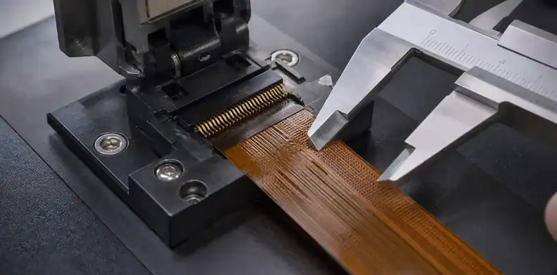
ZIF and FFC/FPC connectors often care about the finished tail thickness, not only the copper pattern. A flex tail that is too thin may not clamp reliably. A tail that is too thick may damage the connector or refuse to insert. The buyer should use the connector drawing as the control document.
The RFQ should state target finished thickness at the insertion area, allowed tolerance, contact side, exposed copper orientation, and whether the stiffener sits on the opposite side. This is one of the most common places where a supplier can build exactly what the Gerber shows but not what the connector needs.
Connector signal: If the connector drawing names a tail thickness range, copy that range into the flex drawing and supplier RFQ.
When the connector is already selected, send its drawing with the RFQ. When the connector is still open, ask the supplier what tail thickness it can hold and tell the product engineer not to freeze the connector until that answer is reviewed.
Connector fit is a practical place for E-E-A-T style evidence. The buyer can ask for a sample tail measurement, supplier stackup confirmation, or connector insertion check rather than waiting for first-article assembly to reveal the mismatch.
Keep bend zones away from stiffener edges
A stiffener edge creates a stiffness transition. If the product bends at that transition, copper fatigue and coverlay damage become more likely. The drawing should mark the bend zone and keep the stiffener edge away from the active bend area.
The safe distance depends on flex stackup, copper weight, bend radius, dynamic versus static use, coverlay, and assembly handling. The RFQ should therefore ask the supplier to review the stiffener boundary, not only the outline.
| Area | Drawing note | Release check |
|---|---|---|
| ZIF tail | Finished thickness and side | Connector fit confirmed |
| Component island | Stiffener under SMT area | Paste and support reviewed |
| Bend zone | No stiffener edge in active bend | Radius and transition checked |
| Panel edge | Handling tab or support method | Operator handling controlled |
This is also why rigid-flex versus flexible PCB cost is a separate decision. If stiffeners are being used to imitate a rigid-flex construction across many areas, the board architecture may need review rather than another local patch.
A bend area is easiest to protect while the drawing is still open. Once the flex tooling has been released, moving a stiffener edge can affect panel utilization, adhesive tooling, and assembly fixtures.
Specify adhesive and side, not just outline
The stiffener outline is only one part of the specification. The drawing should state the stiffener side, material, thickness, adhesive type if controlled, and whether the edge needs special care. Without side information, a mirrored build can still look plausible during a fast RFQ review.
Adhesive matters because it becomes part of the finished thickness and thermal or process behavior. For soldered component areas, the assembly profile may also matter. For connector tails, adhesive squeeze, edge burrs, and thickness stack can change fit.
Drawing rule: A useful stiffener note includes side, material, thickness, adhesive assumption, and the datum used to locate it.
The buyer should not rely on a screenshot or a red box in an email as the only stiffener instruction. Put the note into the released fabrication drawing or controlled assembly drawing so repeat orders do not depend on memory.
Side control deserves a drawing view. A stiffener on the wrong side can still match the two-dimensional outline, so the released document should make top, bottom, and contact orientation clear.
Ask assembly what it needs before quotation
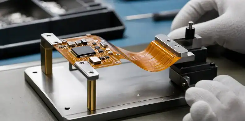
Assembly teams care about how the flex is held, how components are supported, whether the stiffener creates height conflict, and whether the part can be tested without damage. A stiffener that helps connector insertion can create a fixture problem if it changes local thickness or rigidity in the wrong place.
For PCBA, the quote should include fixture assumptions, pallet needs, component keep-out, test handling, and packaging. If the flex will be folded after assembly, the release package should state the fold direction and any post-assembly bend limits.
Before release, review the stiffener with the same people who will touch the assembly. The assembly engineer should confirm whether the stiffened area will be soldered. The manufacturing owner should confirm whether the tail will be inserted by hand or by fixture. The design engineer should confirm the fold direction and bend boundary. If test clamps touch the reinforced tail, the test owner should check fixture pressure before the quote is frozen.
When routing, pockets, or special depth control sit near the stiffened area, connect the review to PCB controlled-depth routing requirements so fabrication and assembly do not make separate assumptions.
Assembly call: Treat the stiffener as part of the PCBA process when it affects placement, fixture, fold, or test handling.
Assembly review should happen before price approval when the flex carries fine-pitch connectors or fragile components. The lowest bare flex price may be false economy if the assembler needs extra handling labor to keep it flat.
Write a stiffener RFQ note that can be built twice
A repeatable RFQ note should identify the stiffener by zone, side, material, thickness, adhesive, finished tail thickness, connector drawing, and inspection evidence. It should also state whether supplier-proposed alternatives are allowed before CAM release.
Useful wording: Please quote this flex PCB stiffener with FR4, PI, or stainless material as shown, including side, thickness, adhesive assumption, ZIF tail finished thickness, bend keep-out review, and any supplier concern before production release.
Record rule: The accepted stiffener interpretation should stay with the released drawing and PO, not only in the supplier’s email reply.
That record gives purchasing a clean way to compare suppliers. It also gives engineering a way to approve a substitution without accidentally changing connector fit.
For repeat orders, keep the approved stiffener interpretation with the PO. If a supplier changes adhesive or thickness on a later run, receiving and assembly need a record that shows whether the change was allowed.
For buyer teams, the cleanest internal record is a one-page stiffener table attached to the RFQ. It should list each stiffened zone, material, thickness, side, connector or assembly purpose, and approval owner. That table helps purchasing compare quotes without asking engineering to reread the whole drawing package.
For engineering teams, the most useful review is often a redline before CAM. Mark the exact tail, component island, and bend area where the supplier must not guess. A supplier that asks a precise CAM question about side or thickness is usually protecting the build, not creating delay.
For founders or product owners, stiffener decisions should be tied to product risk. A wearable, handheld device, sensor cable, or display ribbon may be bent by users for years. A stiffener that only makes first assembly easy but creates a fatigue point near the fold can become a warranty issue.
If the project has a known failure mode, include it in the RFQ note. For example, a tail that backed out of a connector, a cracked solder joint near a fold, or a fixture that crushed the flex area gives the supplier a real design target. That information is more useful than asking for a stronger stiffener without naming the original problem.
When the first samples arrive, receiving should not only count pieces. Check the stiffener side, visual alignment, tail thickness, adhesive edge condition, and whether the flex bends at the intended area. A small sample checklist catches the kinds of mistakes that do not show up in a normal copper inspection report.
FAQ
What is the best stiffener material for a flex PCB?
Choose the material by function. FR4 is common for connector and component support, polyimide suits thinner local reinforcement, and steel belongs where higher rigidity or special mechanics are needed.
How thick should a ZIF flex tail be?
Use the connector manufacturer’s accepted tail thickness range. The flex PCB drawing should state the finished tail thickness and the stiffener side instead of leaving the supplier to infer it.
Can the supplier choose the flex PCB stiffener?
Yes, the supplier can propose a stiffener, but engineering should approve material, side, thickness, adhesive, and bend boundary before production.
Should stiffener details be in Gerber or drawing notes?
Put the controlled requirement in a fabrication or assembly drawing note. Gerbers show geometry, but they rarely communicate the mechanical reason or approval boundary clearly enough.
Related QueenEMS articles
- Flexible PCB manufacturing support
- Rigid-flex versus flexible PCB cost
- Controlled-depth routing requirements
Send QueenEMS the flex stiffener package
If your PCB or PCBA project uses a flex PCB stiffener, contact QueenEMS with the flex drawing, connector drawing, target tail thickness, stiffener material preference, fold direction, component area, quantity, and assembly plan. We can help review whether the stiffener note is quote-ready and whether the supplier needs a CAM question before release.
Include the supplier’s proposed material and side if you already have a quote. The useful review is often a small correction before tooling, not a large redesign after connector fit fails.
Sources
Written by the QueenEMS Engineering Team
Upload your files today · Free DFM check before production · Ship worldwide
Get your PCB prototypes in as fast as 24 hours. We handle FR4, Rogers, and Flex up to 60 layers — free prototypes for 2–4 layer boards, no minimum order.
Just upload your Gerber + BOM — we source every part, assemble, and inspect (AOI + X‑Ray) so you don't have to chase suppliers. Boards ship in as fast as 24 hours.