
Quick Answer: The rigid-flex vs flexible pcb cost difference is massive: a standard 2-layer flexible PCB prototype costs roughly $100 to $200, while a 4-layer rigid-flex board starts at $1,500 for just 5 pieces. You pay a 500% to 1000% premium for rigid-flex because combining dissimilar materials with different thermal expansion rates drastically lowers the lamination yield rate on the factory floor. Key takeaways:
- Rigid-flex prototyping typically starts at $1,500+ due to complex setup and alignment tolerances.
- Pure flexible PCBs are 80% cheaper and can handle high-volume production under $2 per unit.
- Adding FR4 stiffeners to a standard flex board mimics rigid-flex strength at a fraction of the price.
- Specifying custom prepreg thicknesses on flex layers instantly doubles your fabrication cost.
- Assembling components on rigid-flex requires custom SMT carriers, increasing labor costs by 20% to 40%.
Table of Contents
- What Drives the Rigid-Flex vs Flexible PCB Cost Difference?
- Flexible PCB vs Rigid-Flex: What Are the Exact Cost Differences?
- Why Is the NRE Tooling Cost So High for Rigid-Flex?
- Does Rigid-Flex Increase Your PCB Assembly (PCBA) Cost?
- Rigid-Flex vs Cables: Which is Cheaper to Manufacture?
- What Are the Cost-Saving Alternatives to Rigid-Flex?
- How Can You Reduce the Cost of a Flexible PCB Design?
- When Is Rigid-Flex Actually Worth the Premium Price?
- FAQ
You just uploaded your Gerbers for a new compact device, expecting a standard $150 prototype bill. Instead, the quote comes back at $1,800 simply because you checked the “rigid-flex” box on the order form. Sound familiar? Hardware forums are flooded with engineers suffering sticker shock over hybrid boards. After processing hundreds of flexible and rigid-flex orders last year, we see startups constantly burning their budgets on unnecessary stack-ups. Here’s exactly what drives that extreme price gap — and how to get the mechanical fit you need without draining your funding.
What Drives the Rigid-Flex vs Flexible PCB Cost Difference?
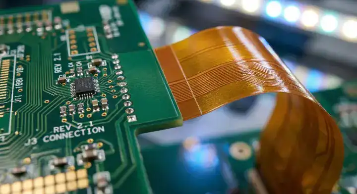
The rigid-flex vs flexible pcb cost gap exists because pressing rigid FR4 and flexible polyimide (PI) together requires over 20 distinct manufacturing steps, driving the factory lamination yield rate down by 20% to 30%. A standard flexible PCB simply etches copper onto PI, skipping the brutal thermal stress of hybrid pressing entirely.
Here’s where it gets real…
On hardware engineering forums like EEVblog, designers constantly ask why 5 pieces of a small rigid-flex board cost $1,500. The answer is material alignment. When you combine rigid and flex materials, the factory must align the layers at microscopic tolerances while dealing with plasma desmear processes to clean the via holes. Board houses actively price a high failure rate into your quote because they know they will likely have to scrap and rebuild at least one panel.
- Different coefficients of thermal expansion (CTE) cause the board to warp or shear vias during the hot press cycle.
- Rigid-flex requires laser-cut prepreg and multiple lamination cycles, taking 10 to 15 days instead of 3.
- Pure flex boards skip the rigid milling process entirely, making them incredibly cheap for high-volume runs.
Flexible PCB vs Rigid-Flex: What Are the Exact Cost Differences?
Standard flexible PCBs cost roughly $2 to $5 per unit at medium volumes, whereas the equivalent rigid-flex board will run you $15 to $40 per unit depending on the layer count. Prototyping amplifies this gap, pushing a hybrid board setup fee well past $1,000 before a single component is soldered.
So what does this actually mean for your budget?
If your product lifecycle requires thousands of units, choosing the wrong substrate early on destroys your profit margins. Take a look at the raw fabrication differences before you commit to a hybrid design. Notice how the tooling costs disproportionately hurt small prototype runs.
| Cost Factor | Pure Flexible PCB (2-Layer) | Rigid-Flex (4-Layer Hybrid) |
|---|---|---|
| Prototype Setup Fee (NRE) | $100 – $250 | $1,500 – $2,500 |
| High-Volume Unit Price | $1.50 – $4.00 | $12.00 – $35.00+ |
| Lead Time (Prototypes) | 3 – 5 Days | 12 – 18 Days |
| Panel Utilization | High (Can nest odd shapes) | Low (Rigid sections waste space) |
Upload your BOM and Gerbers today for a free DFM review. Our engineering team will tell you exactly which technology fits your budget constraints.
Why Is the NRE Tooling Cost So High for Rigid-Flex?
The NRE tooling cost for rigid-flex boards routinely exceeds $1,000 because factories must program expensive laser routing machines to cut the flexible polyimide coverlays and create custom hard-tooling alignment pins to keep the dissimilar materials perfectly registered during lamination. Standard rigid boards just use cheap mechanical drill bits and routers, cutting NRE costs down to $150.
The real question is…
Are you paying for tooling you don’t actually need? Many engineers assume NRE is just an arbitrary “setup fee” that factories charge to turn on the machines. In reality, rigid-flex NRE pays for sacrificial materials. To press a rigid-flex board, we must apply custom conformable release films and Teflon sheets that absorb the uneven pressure caused by the differing thicknesses of the rigid and flex zones. These materials are thrown away after a single use.
- Laser cutting a polyimide coverlay takes 5 times longer than mechanically routing an FR4 solder mask.
- Custom steel alignment fixtures must be fabricated specifically for your board’s geometry.
- Every hybrid design requires a unique flying-probe test program to verify that bending the flex section did not break any internal vias.
Does Rigid-Flex Increase Your PCB Assembly (PCBA) Cost?
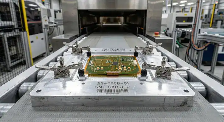
Yes, assembling components onto a rigid-flex or pure flexible board increases your PCBA labor and tooling costs by 20% to 40% because the factory must manufacture custom thermal carriers to hold the flexible sections flat while traveling through the SMT reflow oven. Without these expensive magnetic pallets, the flexible polyimide will curl under high heat and destroy your solder joints.
Now, here’s the part that surprises most customers…
Startups constantly budget for the expensive bare board but totally forget that SMT assembly for flex materials is notoriously difficult. Customers often complain when quoted an extra $400 for assembly tooling on a flex order. We show them that their components will literally slide off the board during reflow if we don’t mill a custom aluminum jig to hold the panel perfectly rigid.
- 90% of flexible boards require custom SMT carriers, adding 2 to 3 days to your assembly lead time.
- Applying solder paste to an uneven rigid-flex surface requires specialized stepped stencils.
- We run strict 3D AOI and X-Ray inspections on every rigid-flex BGA joint because the material transition zones are highly prone to warping and lifting during cooldown.
Rigid-Flex vs Cables: Which is Cheaper to Manufacture?
Using two standard 4-layer FR4 boards connected by a $0.50 FFC (Flexible Flat Cable) is up to 70% cheaper in bare board fabrication than building a single 6-layer rigid-flex board. However, you must factor in the manual assembly time and the physical space required for two bulky ZIF connectors on your PCB.
Here’s the thing…
Hardware startups often assume that eliminating physical wire harnesses automatically saves money. While it does save manual labor during final box build, the massive premium you pay for hybrid PCB lamination usually wipes out any labor savings.
- Cable assemblies require physical ZIF connectors, taking up valuable real estate on your PCB.
- Physical connectors are the #1 point of failure in high-vibration environments.
- If you have plenty of physical vertical space inside your enclosure, separate rigid boards with a ribbon cable are almost always your cheapest path to market.
What Are the Cost-Saving Alternatives to Rigid-Flex?
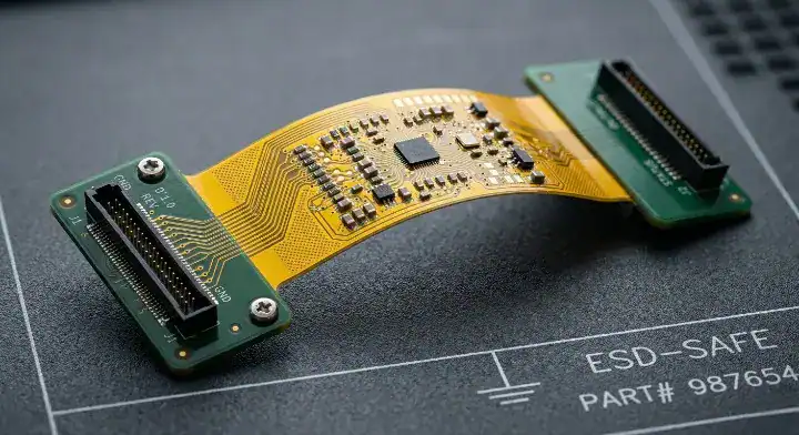
You can replace an expensive rigid-flex board by using a continuous flexible PCB and attaching thick FR4 stiffeners to the areas where components are mounted, saving you up to 80% on fabrication costs. The stiffeners provide the exact same physical support for heavy connectors or BGAs without requiring complex hybrid lamination.
But here’s what most guides won’t tell you…
80% of first-time customers request a 6-layer rigid-flex quote for a “bend-once-to-install” application inside a static enclosure. This is a massive waste of money. We built a specific DFM process to flag these exact designs. We switch them to a multi-layer pure flex board supported by 1.6mm FR4 stiffeners on the component ends. This single change cuts their PCB prototyping cost from $1,800 to under $300 while achieving the exact same mechanical fit.
- FR4 stiffeners add rigidity specifically behind connectors to prevent insertion damage.
- Polyimide (PI) stiffeners increase the thickness specifically to meet ZIF connector tolerances.
- Standard stainless steel stiffeners can be used for extra heat dissipation under power LEDs.
How Can You Reduce the Cost of a Flexible PCB Design?
You reduce flexible PCB costs by strictly using the manufacturer’s standard stack-up thickness and defaulting to standard Electrodeposited (ED) copper instead of premium Rolled Annealed (RA) copper. Forcing a board house to order unstocked, non-standard material thicknesses adds hundreds of dollars and weeks of delay to your project.
Want the honest answer?
Engineers often specify a highly specific thickness to match a mechanical enclosure slot. On StackExchange, veterans constantly warn against this. If you demand an exact 0.15mm flex thickness instead of the factory standard 0.11mm, the purchasing team has to hunt down niche materials.
- Use RA (Rolled Annealed) copper only if your board undergoes continuous, dynamic bending (like a printer head).
- Use standard ED (Electrodeposited) copper for static, “bend-once” installations to save 15% on material costs.
- Always keep your flex routing simple. Avoid sharp 90-degree traces that cause stress fractures during bending.
- Never place vias directly in the bend radius of the flexible section.
When Is Rigid-Flex Actually Worth the Premium Price?
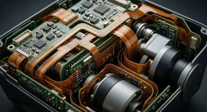
Rigid-flex justifies its high cost when your product faces extreme vibration, requires thousands of dynamic bending cycles, or demands high-density routing in a severely constrained space like a medical implant or aerospace sensor. In these specific environments, eliminating physical connectors drastically improves signal integrity and long-term reliability.
So, what is the final verdict?
Are you bending the board once during assembly, or will it bend every time the user opens the device? If your hardware lives in a laptop hinge, a camera gimbal, or a robotic arm, the upfront cost of rigid-flex pays for itself by preventing field failures.
| Scenario | Recommendation | Why? |
|---|---|---|
| Smartwatch / Wearable | Rigid-Flex or HDI PCB | Extreme space constraints require hybrid technology. |
| Medical Endoscope | Rigid-Flex | Eliminating connectors prevents catastrophic failure during use. |
| Keyboard / Simple Display | Flexible PCB + Stiffener | Static installation; no need to pay for hybrid lamination. |
| Industrial Sensor Box | Two Rigid Boards + Cable | Plenty of space; cheapest and easiest method to manufacture. |
If you are developing critical hardware for medical assembly, do not guess your material reliability. Request a free first-article inspection on your first order.
FAQ
Can I put vias in the flexible section of my board? Yes, you can place vias in the flexible area, but you must avoid putting them directly inside the active bend radius. Bending stresses the via barrel, easily causing microscopic cracks and intermittent electrical failures over time. Keep all vias in the static, flat portions of the flex design.
Are stiffeners the same thing as rigid-flex? No, they are totally different technologies. A stiffener is just a piece of blank FR4 or Polyimide glued to the outside of a flexible board to make it locally stiff. Rigid-flex actually embeds the flexible layers inside the rigid FR4 core, allowing plated through-holes to connect all layers together electrically.
Can I use standard FR4 for the rigid part of a rigid-flex board? Yes, but you should specify a high-Tg FR4 material (like 370HR) rather than standard Tg-130 FR4. The hybrid pressing process exposes the materials to extreme thermal stress, and standard FR4 may delaminate or blister during the extended high-temperature lamination cycles.
How many bend cycles can a flexible PCB survive? It depends on your copper type and bend radius. A well-designed flex board using rolled annealed (RA) copper can survive millions of dynamic bend cycles, making it perfect for printer heads or robotics. Standard electrodeposited (ED) copper is only meant for static, “bend-once” installations. Upload your mechanical drawing to let us calculate your safe bend radius.
Written by the QueenEMS Engineering Team. Ready to build your next board? Contact us today at QueenEMS.
Upload your files today · Free DFM check before production · Ship worldwide
Get your PCB prototypes in as fast as 24 hours. We handle FR4, Rogers, and Flex up to 60 layers — free prototypes for 2–4 layer boards, no minimum order.
Just upload your Gerber + BOM — we source every part, assemble, and inspect (AOI + X‑Ray) so you don't have to chase suppliers. Boards ship in as fast as 24 hours.