

Quick Answer: A QR code on PCB needs an agreed payload, enough room for its complete module grid and quiet zone, a suitable marking process and a clear view for the intended reader. Standard QR symbols require a four-module quiet zone on every side. Qualify the marked board after the production operations it will actually encounter; a successful phone scan of bare-board artwork is not sufficient evidence.
A QR code on PCB can look sharp in CAD yet become unreadable after manufacture or assembly. Small modules merge, a connector covers a corner, or coating turns a previously readable surface into a reflective one. The practical design task is to protect the symbol through the route in which it must be read.
This article addresses standard QR symbols, not every two-dimensional code or Micro QR variant. It does not assume a universal minimum size or claim that placing a symbol automatically creates a traceability system.
Table of Contents
- What should the board symbol identify?
- Shorten the payload before choosing the symbol
- Calculate the entire footprint, including the quiet zone
- Choose legend printing, laser marking or a label
- Place the code where it remains visible
- Protect the module grid in CAD and manufacturing files
- Match lighting and optics to the marked surface
- Distinguish successful decoding from verification
- Qualify readability through the production route
- Prepare the QR marking package for your quote
What should the board symbol identify?
Decide whether the QR code on PCB identifies a design, a production lot or one physical unit. A shared documentation link and a unique serial number have different marking requirements, even when both use a QR symbol.
A fixed legend can direct every board of one revision to the same instructions. It cannot distinguish individual boards unless some other identifier supplies that distinction. If the payload must change for every unit, the manufacturing route needs a variable-data operation and a defined association between the mark and the board being processed.
The physical symbol is only an access point to information. The PCB lot traceability records determine what a retrieved identifier actually connects to. Keep the marking requirement separate from database retention and genealogy rules so the fabrication drawing does not become a substitute for either.
Name the intended reader and reading stage early. A service technician scanning an open enclosure with a phone has different access from an installed camera reading a moving panel. Specify whether the code must be readable before assembly, after depanelization, during final test or after service exposure.
Also decide what information may be public. Encoding a secret credential or customer-sensitive production record directly into a visible symbol makes it available to anyone who can photograph the board. A short identifier with controlled lookup may be preferable, but the lookup system still needs its own access and continuity plan. Select the identity model before reserving artwork space.

Shorten the payload before choosing the symbol
Generate the symbol from the released payload and error-correction setting before committing to its dimensions. Character type, data length and encoding choices affect the version and number of modules.
Encode the stable identifier
A short controlled identifier generally demands less symbol area than a long URL containing descriptive fields and tracking parameters. Remove unnecessary data rather than shrinking the same dense grid until it barely fits. Check the longest permitted payload, not just a convenient short example.
A URL whose destination can change is not necessarily a unique unit identifier. The same redirect address printed on every PCB is still shared. Conversely, a fixed string containing a unique serial can identify one unit without using a redirect service. Specify these axes separately to avoid ordering identical marks when serialization was intended.
Choose error correction with the marking process
DENSO WAVE explains that increasing error correction also increases the encoded data requirement. Its recovery percentages concern codewords, not permission to erase the same percentage of the symbol’s physical area. Quiet zones, finder patterns and adequate contrast still matter.
Compare actual generated candidates using the intended reader and surface. A higher setting may require a larger version and therefore smaller modules in the same footprint. That tradeoff can make a difficult marking process worse rather than automatically improving it.
When the code is meant to match programmed device identity, coordinate the marking data with the firmware programming release package. Freeze a representative payload set, including edge cases, before the artwork or variable-marking recipe is approved.

Calculate the entire footprint, including the quiet zone
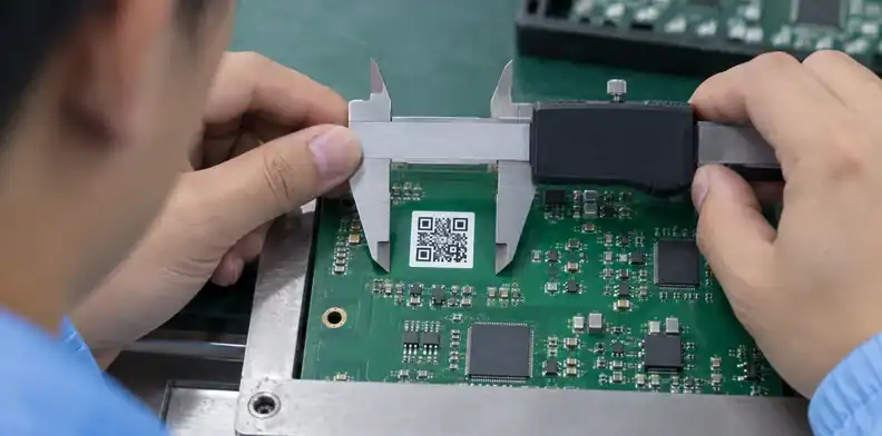
Reserve the matrix and its border together. For a standard QR symbol with N modules per side and module width X, a four-module border on each side makes the total width W = (N + 8) × X.
Version 1 has 21 modules per side; each subsequent version adds four. Thus N = 21 + 4 × (version − 1). These are symbol dimensions, not a PCB manufacturer’s minimum printable feature or a guarantee of scanner performance.
Consider an illustrative drawing that allows 8.00 mm total, including the quiet zone:
| Generated version | Matrix modules per side | Module width within 8.00 mm total | Total width if X = 0.25 mm |
|---|---|---|---|
| Version 1 | 21 | 0.276 mm | 7.25 mm |
| Version 3 | 29 | 0.216 mm | 9.25 mm |
| Version 4 | 33 | 0.195 mm | 10.25 mm |
The 0.25 mm value is hypothetical, not a QueenEMS capability or a general acceptance limit. If a particular qualified marking-and-reader combination needed that width, only the Version 1 candidate would fit this allocation.
“8 mm QR” is ambiguous. If 8.00 mm describes only a Version 3 matrix, the complete footprint is 37 × 8/29 = 10.21 mm. Put the dimension’s meaning on the drawing. When the generated code exceeds the available area, shorten the payload, enlarge the keepout or qualify a different process; do not silently sacrifice the required border.
Choose legend printing, laser marking or a label
Choose the method according to fixed versus variable data, the actual surface and the exposures before the final required scan. No method is automatically permanent or readable on every PCB material.
| Method | Useful application | Qualification concern |
|---|---|---|
| Legend printing | Fixed code shared by a design or revision | Feature reproduction, ink spread, contrast and CAM changes |
| Laser marking | Variable or fixed direct marking on a qualified surface | Material response, depth, damage risk and post-process contrast |
| Variable ink printing | Serial data without a fixed legend image | Adhesion, curing, solvent exposure and module definition |
| Qualified label | A readable contrasting surface with flexible placement | Exact adhesive, ribbon, temperature, cleaning and attachment |
For a legend code, review the general PCB silkscreen manufacturing requirements. QR geometry needs more protection than ordinary readable text because module merging or clipping can change the symbol itself.
Laser marking should be trialed on the intended mask, laminate or other selected surface. A clean-looking mark does not establish that the process avoided underlying damage, and favorable results on one color or formulation do not qualify another. Document the allowed marking region and the checks needed for the product.
For labels, specify the complete material-and-print combination rather than simply “polyimide.” Adhesive, ribbon and cleaning chemistry can change the result. A label attached after reflow does not prove that the same label would survive reflow. Select the process stage as part of the method decision, then qualify samples through the remaining exposures.

Place the code where it remains visible
Check line of sight on the completed assembly and in the actual reader fixture. A free patch of bare-board space is not necessarily a usable scan location once connectors, shields and cables are installed.
Review the code’s whole footprint in the mechanical model, including its quiet zone. Keep components, test probes, fixture clamps and panel supports from covering it at the required station. Consider the reader’s view angle and working distance, not only whether the mark appears visible in a top-down screenshot.
Do not place the only permanent unit identifier on a break-off rail. A rail mark may be useful for panel handling, but the association must be preserved when units separate. If a final-test station reads individual boards, its code needs to remain on the shipped unit and stay accessible in that station.
The mark is not an SMT alignment reference. Reserve the necessary assembly fiducial locations independently, and check that any marking operation does not interfere with them. A camera that reads a code is performing a different task from a placement camera recognizing a fiducial.
Placement can also fail later in service. A code beneath an installed battery may be reachable only after disassembly, which could conflict with the intended maintenance task. Show the required access condition on the assembly drawing. Where two reading stages need incompatible locations, review whether a second identifier or a different data-access method is justified rather than leaving the conflict for the operator.

Protect the module grid in CAD and manufacturing files
Use a controlled symbol object or validated import, then inspect the final manufacturing output. A readable image pasted into CAD is not proof that the exported geometry preserves its modules and border.
Keep generation and scaling under control
Some EDA tools support native QR objects; others need an import workflow. Altium’s current documentation describes barcode objects with module or overall-width control. DXF is therefore one possible workflow, not an obligatory intermediate format for every design tool.
Avoid uncontrolled raster resizing, antialiasing or edits that round module boundaries. Check polarity, side, orientation and any mirroring in the actual exported layer. Decode the released artwork and compare the resulting string character for character with the intended payload.
The final CAM review should retain the quiet zone and prevent automatic clipping around pads or other features. If cleanup changes the symbol, regenerate or requalify it rather than assuming error correction will absorb the alteration. Keep an approved rendered reference with the released files.
Specify variable marking separately from Gerbers
A fixed fabrication image does not describe a changing serial sequence. Supply the variable-data format, permitted characters, longest payload, assignment rule and duplicate handling in a separate marking specification.
Define how the mark is associated with each board position and how skipped or rejected units are handled. The adjacent panel and unit identification discussion covers the record relationship. Here the manufacturing requirement should make the expected physical mark and decoded string unambiguous, without attempting to describe the entire database system.

Match lighting and optics to the marked surface
Qualify the reader with the real surface, geometry and motion. Phone readability under convenient room lighting does not establish performance at a fixed industrial camera’s distance, angle or exposure time.
| No-read pattern | Useful confirming check | Candidate action to evaluate |
|---|---|---|
| Reads at one angle only | Compare glare across the required orientations | Adjust lighting or qualified reader geometry |
| Fine modules blur in motion | Inspect focus, pixel coverage and dwell | Reconsider optics, speed or physical size |
| Reads before coating, fails afterward | Examine the coated surface under station light | Qualify a coating keepout or altered marking route |
| Only one board color struggles | Compare actual contrast and surface response | Trial a different mark or lighting arrangement |
| Camera cannot see a corner | Check the assembled fixture view | Relocate the complete footprint or remove obstruction |
Keep the test conditions in the approval record. Working distance, orientation, lighting arrangement and board speed are part of the evidence, not incidental details. A successful bench scan becomes difficult to reproduce when none of those conditions are retained.
Compare failed units with readable units from the same process stage. If both have similar module geometry but only one exhibits glare, changing the payload is unlikely to address the immediate optical cause. If modules merge physically, changing lighting may improve appearance without restoring the intended geometry.
Also distinguish a successful decode from a failed lookup. A reader may return the correct URL while the server is unavailable. That is a data-service problem, not necessarily a marking defect. The investigation should record the decoded value before changing the artwork or replacing labels.

Distinguish successful decoding from verification
Production-reader trials and formal symbol verification provide different evidence. Retain actual-reader qualification and add formal grading when the product requires it; do not describe every vendor quality score as an ISO-compliant report.
Test the production reader
Use the installed reader to check the intended payload at relevant positions, orientations and cycle conditions. Record reads, no-reads and retries over an agreed sample and number of attempts. Define the denominator so a report cannot hide failed first reads behind unlimited retries.
Check the decoded identity against the expected unit, not merely the presence of any readable string. A perfectly readable duplicate serial is still the wrong manufacturing result. Where scanning accompanies test, align identity handling with the assembly inspection and test scope.
Request a stated verification method
Formal verification evaluates defined quality parameters under specified measurement conditions. The applicable method depends on the symbol and marking application. The current ISO/IEC 29158:2025 listing describes direct-part-mark measurement and reporting; the required method, edition and acceptance grade should be stated by the controlling specification.
Cognex’s verifier documentation also distinguishes compliant verification from flexible standards-based grading that approximates it. Ask what the supplied report actually represents, including calibration and illumination conditions. Neither a proprietary score nor a generic minimum grade should be assumed for every PCB. Where formal grading is unnecessary, preserve the agreed actual-reader qualification rather than implying a certification that was not performed.

Qualify readability through the production route
Test the symbol after the operations it must survive and at the last required reading point. Approval immediately after marking leaves later thermal, chemical and mechanical changes untested.
| Checkpoint | What to examine | Evidence to retain |
|---|---|---|
| Immediately after marking | Module definition, border and payload | Mark image and decoded value |
| After assembly heating | Contrast, label attachment, surface change | Same-sample scan under agreed conditions |
| After cleaning | Ink, adhesive and residue effects | Chemistry, route and post-cleaning result |
| After coating or depanelization | Optical access and physical survival | Final-stage image and reader trial |
| At final test or service access | Fixture view, identity and reader conditions | Approved scan setup and disposition |
Consider an illustrative review, not a QueenEMS customer case: a phone reads the clean bare board, but a shield blocks one corner after assembly. Relocating the full footprint may solve the access issue; selecting stronger error correction does not remove the shield.
A second illustrative sample reads before coating but fails under the production light afterward. Compare glare and contrast before blaming the encoded data. Any revised marking location, coating keepout or lighting arrangement needs the same downstream qualification.
Cleaning deserves particular attention when a mark sits near process residues. The PCB cleanliness testing context addresses a different property: residue control is not evidence of code readability. Retest when the marking material, surface, payload version, coating or reader setup changes in a way that could affect the approved result.

Prepare the QR marking package for your quote
Send the supplier a marking specification that joins the encoded data, physical geometry and scan conditions. “Add a QR code” leaves too many decisions unresolved for a comparable quotation.
| Item to supply | Detail that avoids ambiguity |
|---|---|
| Payload examples | Released strings, longest case and fixed or variable rule |
| Symbol definition | Standard QR type, generated version and error correction |
| Layout | Board side, coordinates, total footprint and quiet zone |
| Marking surface | Actual mask, laminate, finish or selected label combination |
| Production route | Heating, cleaning, coating and depanelization before final read |
| Acceptance evidence | Reader conditions, sample plan and any required verification method |
Include the assembled view and fixture constraints when access is tight. If the supplier proposes a smaller mark, ask which module size, full border and actual reader evidence support the proposal. A line-width capability statement alone does not answer that question.
For variable data, provide the assignment and exception rules before pricing. Fixed artwork, unique laser marks and applied labels involve different operations; the supplier needs to quote the route that will actually identify your boards.
Bring the layout, representative payloads and intended scan conditions to QueenEMS for a PCB marking quotation. Those inputs support review of the marking method, reserved footprint and qualification work needed for the build. The resulting proposal should identify remaining sample tests, rather than promise that a generic code size will scan under every future condition.
Sources
- DENSO WAVE: QR symbol area and four-module quiet zones.
- ISO/IEC 29158:2025: direct-part-mark quality measurement.
Written by the QueenEMS Engineering Team
Upload your files today · Free DFM check before production · Ship worldwide
Get your PCB prototypes in as fast as 24 hours. We handle FR4, Rogers, and hybrid boards up to 40 layers in volume production, with advanced builds subject to engineering review — free prototypes for 2–4 layer FR-4 boards, no minimum order.
Just upload your Gerber + BOM — we source every part, assemble, and inspect (AOI + X‑Ray) so you don't have to chase suppliers. Boards ship in as fast as 24 hours.