
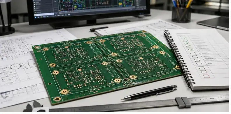
Quick answer: Fiducials are assembly vision targets, so the useful requirement is not merely “add fiducials.” Identify which PCB side will be assembled, whether the machine aligns to the individual board or the production panel, and which fine-pitch areas need local correction.
Key takeaways
• Separate board, panel, and component-level alignment.
• Keep each target optically clean and visible in the delivered data.
• Review panel rails with the assembler before bare-board release.
• Freeze any approved fiducial change with the centroid and assembly drawing revisions.
Fiducial SERPs often collapse the subject into mark diameter and count. For procurement, the decisive information is the assembly configuration: single board or panel, processed side, placement accuracy, camera access, and the components that need local correction.
This guide therefore follows the fiducial from CAD through panelization to the SMT machine. It helps the buyer decide what belongs in fabrication data, what the assembler must confirm, and which changes should reopen the assembly review.
This topic sits between PCB fabrication and PCBA setup. A PCB can be fabricated correctly and still be inconvenient for SMT if fiducials are missing, hidden by mask, too close to components, or absent from the panel rails. Buyers should therefore review fiducials before ordering boards for assembly.
Assembly-readiness path
- Why do fiducials matter before assembly?
- What is the difference between global and local fiducials?
- What geometry and clearance should be reviewed?
- How do panels and rails change fiducial planning?
- What should buyers ask before PCBA quotation?
- What should the fiducial RFQ package include?
Why do fiducials matter before assembly?
Fiducials help SMT equipment locate the board, panel, or local component area accurately. They become important when the board has fine-pitch parts, BGAs, dense placement, panelized assembly, or local alignment challenges. If fiducials are missing or poorly designed, assembly may slow down or require manual workaround.
SERP and AI answers consistently separate global, local, and panel fiducials. For RFQ work, the buyer should not ask only whether fiducials exist; the better question is whether the assembly plan has the right marks for the board side, panel rails, fine-pitch or BGA areas, and stencil/pick-and-place alignment. Common guidance often mentions two or three global fiducials and local fiducials near fine-pitch parts, but the final rule should come from the assembler’s equipment and panel plan.
A fiducial decision belongs in the assembly record because the bare-board fabricator cannot infer the placement machine, camera field, or panel handling plan. The PCBA supplier should state whether it will use board marks, rail marks, local targets, or a documented machine workaround for this exact revision.
For assembly file preparation, connect this article to PCBA RFQ files. For bare-board manufacturing inputs, use PCB fabrication quote files. The key is to avoid having the PCB supplier and assembler make different assumptions.
What is the difference between global and local fiducials?
Global fiducials help the machine locate the board or panel. Local fiducials help locate a critical component area such as BGA, fine-pitch connector, or dense module. The buyer should not assume one type replaces the other. The assembly process and component risk should decide what is required.
Moving a fiducial is not a harmless CAM cleanup. It can change the coordinate relationship used by stencil printing and placement. The assembly owner should approve the revised copper, mask opening, panel drawing, and centroid origin together before the fabricator releases tooling.
If a fiducial issue appears after DFM, use PCB CAM questions to decide whether the data can be clarified or must be revised. A new fiducial location may affect Gerbers, panel rails, or assembly setup, so it should be controlled.
What geometry and clearance should be reviewed?
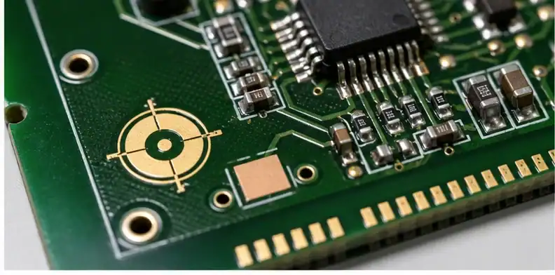
A fiducial usually needs a clean copper mark with solder mask clearance and enough surrounding space for the vision system. The exact size and clearance depend on assembly capability and machine rules. The RFQ should ask the assembler or PCBA supplier to review whether the marks are visible, clean, and placed logically for the panel.
A vision target should be judged by what the camera sees: exposed contrast, an uncluttered perimeter, stable location, and availability on the side being processed. Copper shape alone is not enough if solder mask, legend ink, a clamp, a component body, or a panel breakaway obscures the optical scene.
How do panels and rails change fiducial planning?
Panel fiducials may be placed on rails, while board-level fiducials may remain on each circuit. If the panel design changes after PCB fabrication, assembly assumptions can break. Buyers should align PCB panelization and SMT requirements before ordering production panels.
Evidence for fiducials is mostly setup evidence rather than a thick inspection report. A panel image, Gerber view, and assembly-program review can show that the marks are present and usable; first-off placement results become more valuable when BGAs, QFNs, or fine-pitch connectors drive alignment risk.
What should buyers ask before PCBA quotation?
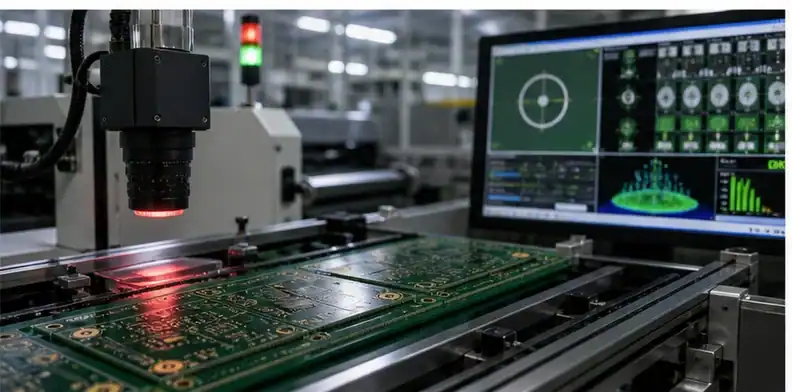
Ask whether the supplied PCB data includes global and local fiducials, whether the assembly house needs rail fiducials, whether any critical components require local marks, and whether solder mask clearance is acceptable. These questions belong before quotation because they affect PCB panel design and assembly setup.
If rail width or board area is tight, compare alternatives with the assembler: alter rail geometry, relocate a local mark, use two usable targets with machine approval, or reserve manual alignment for prototypes. The quotation should name the accepted setup so a low price does not hide extra operator time.
What should the fiducial RFQ package include?
Start with the actual assembly route. State whether the board is supplied as singles or in a panel, which sides receive solder paste and placement, and whether depanelization occurs before or after assembly. That context tells the process engineer which coordinate frame the marks must support.
Provide the released copper, solder-mask, silkscreen, paste, and outline layers together with the assembly drawing, BOM, and centroid file. The centroid origin and rotation convention should agree with the drawing; a fiducial cannot rescue a placement file that references a different origin.
Mark board-level and panel-level targets separately on the panel drawing. If local fiducials are intended for a BGA, QFN, fine-pitch connector, or another placement-sensitive package, identify the component reference and the applicable side. This removes the guesswork created by an unlabeled exposed copper circle.
Ask the assembler to confirm optical suitability, not just count. The review should cover target shape, solder-mask relief, nearby copper or legend clutter, component shadowing, rail clamps, and whether the marks remain available after stencil loading. Machine preferences vary, so the approved drawing should capture the supplier-specific answer.
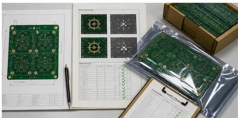
IPC-7351B includes global, panel, local, location, size, and clearance guidance for fiducials. Use the standard as a design reference, then let the selected assembly line validate the exact implementation; the IPC-7351B contents and figures are a useful checkpoint without replacing the project drawing.
For a panel supplied by a different bare-board source, place the assembly house’s rail requirements inside the fabrication package before purchase. Otherwise the board vendor may optimize breakaway tabs or rail width and accidentally remove the vision area that the SMT line expected.
Define the hold conditions narrowly: missing side identification, a mark covered by mask, an origin conflict, or a panel revision that changes target position should stop release. A cosmetic change elsewhere on the rail does not need the same escalation unless it affects camera access or panel handling.
On repeat builds, preserve the approved panel file, centroid revision, first-off placement notes, and any machine-specific exception. If the panel source or assembler changes, reopen the fiducial review because the previous confirmation described a production line, not an abstract PCB capability.
For quotation, send the same package used in the PCBA RFQ checklist and flag the alignment-sensitive packages. QueenEMS can then return one focused DFM response covering the individual circuit, the assembly panel, and local placement areas.
A board-level mark and a rail mark solve different registration problems. The first lets the machine relate placements to one circuit; the second lets it locate the production panel. If only rail targets exist, verify that panel stretch and circuit-to-panel registration remain acceptable for the placement pitch.
Two-side assembly needs a side-by-side review. A target visible on the top may be covered, absent, or mirrored incorrectly on the bottom data. List the marks used for each stencil-print and placement pass instead of treating the PCB as though one camera setup serves both faces.
Local fiducials deserve a functional reason. Place them where the assembler needs correction for a sensitive footprint, then keep the component courtyard, paste deposit, and rework access in view. Adding local marks beside every package can consume routing area without improving a modern machine’s program.
Panel breakaway design can invalidate an otherwise good layout. A V-score line, tab route, tooling hole, clamp zone, or conveyor shadow may cut through the clean optical background. Review a fabrication-ready panel image, not only the original single-board Gerbers.
Solder-mask registration matters because the camera detects contrast at the finished surface. Ask whether the proposed clearance remains clean at the fabrication tolerance and surface finish. Legend ink, exposed test pads, copper pours, or scratches close to the mark can reduce recognition even when the fiducial pad itself is present.
Centroid data should express component position and rotation from a declared origin. During DFM, compare that origin with the board outline and fiducials on a rendered view. This simple overlay catches mirrored coordinates, unexpected bottom-side conventions, and panel offsets before machine programming.
If the assembler plans to add fiducials on removable rails, clarify who owns the panel design and whether the bare-board price includes those rails. A PCB quote based on singles cannot silently become an assembly-ready panel quote without changing material utilization, tooling, and shipment format.
For early prototypes without ideal marks, ask the line to document the workaround and its limits. Slower vision search, edge alignment, or manual correction may be acceptable for learning builds, yet that exception should not become the default production process when volume or component density increases.
First-off approval should look beyond whether components are generally centered. Review the packages most sensitive to translational and rotational error, paste-to-pad registration, and any placement drift across the panel. Record which fiducial set the machine actually used so the evidence is reusable.
A useful supplier answer is concrete: ‘top-side panel alignment uses these rail targets; local correction applies to these references; bottom-side setup uses these board marks.’ That statement is more valuable than a generic confirmation of IPC compliance because it connects the drawing to the chosen line.
When a customer supplies its own panel, preserve the source CAD or intelligent data instead of sending only a flattened image. The assembly engineer may need exact coordinates for targets, tooling holes, circuit step-and-repeat, and breakaway geometry to validate the program.
The purchasing decision is complete when fabrication and assembly agree on the same panel revision. File names, approval screenshots, and email comments should point to that revision; otherwise a correct fiducial response can be applied to an obsolete panel and provide false confidence.
If fiducials are intentionally omitted, record the assembler’s alternative alignment method and the conditions under which it remains valid. Board edge quality, tooling holes, panel rails, camera software, and placement pitch can all limit that exception, so it should be reviewed again when the design or line changes.
Distinguish vision targets from tooling holes and test targets in notes and layer names. They may appear near each other on a rail but serve different equipment. Clear labeling prevents a fabricator from modifying one feature while believing another still provides equivalent alignment.
The final approval package should make one engineer able to answer three questions without opening old email: which marks are used on each side, which panel revision contains them, and which components require local alignment. That is the practical test for a reusable fiducial requirement.
Do not use a fiducial as a convenient drawing datum unless the mechanical and assembly teams agree on that relationship. Vision alignment corrects the machine program from observed targets; it does not automatically make the copper mark the best datum for enclosure dimensions, routing tolerances, or incoming mechanical inspection.
FAQ
Is PCB fiducial requirements required for every PCB order?
No. A hand-assembled prototype or a board with a supplier-approved vision strategy may not need the same marks as a dense automated build. Decide with the assembler from placement pitch, panel format, processed side, and machine setup rather than applying one universal count.
Can the supplier decide the final detail during CAM?
The supplier may propose a location or mask-clearance correction, but the assembly owner should approve it against the panel, centroid, stencil, and component placement data. Treat the accepted CAM image as a controlled assembly input.
How many fiducials should a PCB have?
There is no safe number without the manufacturing route. Distinguish global or panel alignment from local correction, then ask the selected SMT line to confirm the usable arrangement and whether high-accuracy packages need nearby targets.
What should QueenEMS review before quoting?
QueenEMS should see both bare-board and assembly files, the panel preference, processed sides, centroid convention, and any components that make alignment critical. The response should say which targets will be used and identify any data conflict before tooling.
Need a fiducial review tied to the real SMT setup? Send QueenEMS the PCB, panel, assembly drawing, centroid, and component list; include the intended assembler if another factory will run placement.
Upload your files today · Free DFM check before production · Ship worldwide
Get your PCB prototypes in as fast as 24 hours. We handle FR4, Rogers, and Flex up to 60 layers — free prototypes for 2–4 layer boards, no minimum order.
Just upload your Gerber + BOM — we source every part, assemble, and inspect (AOI + X‑Ray) so you don't have to chase suppliers. Boards ship in as fast as 24 hours.