
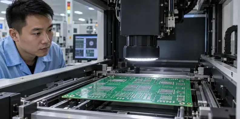
Quick Answer: Solder paste inspection (SPI) checks printed paste on a PCB before components are placed and soldered. Depending on the system, it measures deposit area, position, height and volume to identify printing problems. An SPI pass is evidence about the print, not proof that the finished assembly will pass electrical or reliability testing.
What is solder paste inspection useful for when an assembly quotation already includes automated optical inspection? It provides an earlier opportunity to correct missing, misplaced or excessive deposits before components are placed on the inspected side. Finding the problem after placement or reflow usually leaves fewer recovery options.
For an engineer or buyer, the useful question is therefore not just whether the supplier owns an SPI machine. Ask what the program measures, how its percentages are calculated, which deposits receive special attention and what happens to a rejected print. Those details distinguish a controlled printing process from a report containing unexplained green boxes.
Table of Contents
- Where does SPI belong on the SMT line?
- What can 2D and 3D systems measure?
- Which printed defects need immediate attention?
- How do you read volume percentages correctly?
- What makes an inspection program trustworthy?
- How should paste limits be qualified?
- What causes false calls and missed defects?
- How should a failed print be contained?
- Which records demonstrate printing control?
- What should your assembly RFQ specify?
Where does SPI belong on the SMT line?
Solder paste inspection normally sits after stencil printing and before pick-and-place. At this point the inspection sees deposits on the pads without component bodies hiding them. A failed board can be held for a controlled cleaning and reprint decision rather than progressing automatically into assembly.
Surface-mount technology (SMT) joins three related but different stages: depositing paste, placing components and forming joints during reflow. The SMT assembly process gives the broader production context. SPI addresses the first stage; it cannot directly establish solder wetting, final component orientation or electrical behavior.
Do not assume that every machine is installed inline, that every board is inspected, or that both sides receive the same coverage. A supplier may use an offline inspection station, inspect only initial prints or run a different route for the second side. The quotation should identify which route applies to your build.
Automated optical inspection (AOI) and X-ray answer later questions. A displaced component or hidden joint needs evidence that paste inspection alone cannot provide. When deciding how these methods work together, compare their scope in AOI, X-ray and ICT inspection, rather than treating the technologies as interchangeable.
For a double-sided assembly, keep side-specific program and disposition records. A good print on side one says nothing about a mismatched stencil or setup on side two. This distinction should be visible in the manufacturing route before the first production panel is released.

What can 2D and 3D systems measure?
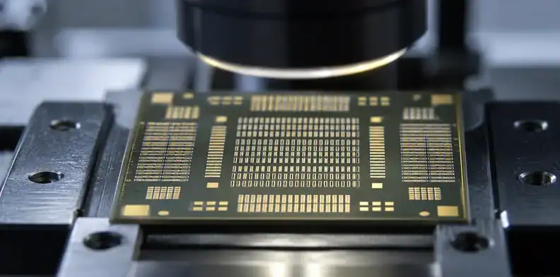
A 2D system primarily evaluates the visible deposit footprint; a 3D system also measures its height profile and derives volume. The available measurements, resolution and compensation functions depend on the actual equipment and program, not simply on the label “3D.”
| Measurement | What it describes | What a buyer should clarify |
|---|---|---|
| Area | Paste footprint within the inspection region | Whether stray paste outside that region is searched |
| Offset | Deposit position relative to its intended location | Reference coordinate, axes and registration method |
| Height | Paste elevation relative to the selected board plane | Plane selection, filtering and threshold settings |
| Volume | Integrated deposit above the chosen reference | Units, nominal denominator and calculation settings |
| Shape or bridging | Relationship between neighboring deposits | Whether the recipe checks the relevant pad gap |
Yamaha’s YSi-SP equipment documentation, for example, describes outline illumination alongside phase-shift 3D measurement. It is an example of complementary measurements, not evidence that every supplier has that particular configuration.
One limitation follows directly from the inspection geometry: a pad-centered region may not include paste smeared into a nearby mask area. Ask to see the regions used on fine-pitch pins and between passive-component pads. A volume value within limits does not rule out unwanted material elsewhere on the board.
Similarly, board curvature can change the apparent reference surface. The engineer needs to distinguish a genuinely tall deposit from a measurement problem caused by an inappropriate plane. A supplier response should name the affected measurement and show the corresponding image, so you can judge whether the proposed adjustment repairs the program or conceals a bad print.
Which printed defects need immediate attention?
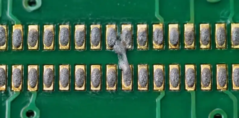
Hold a print when the observed deposit could prevent the intended joint from forming or create an unintended connection. Classify the condition before editing thresholds; a missing deposit and a registration error require different investigations.
| Observed print | Evidence worth retaining | First investigation |
|---|---|---|
| Missing or very small deposit | Aperture image and measured volume | Blockage, release behavior, paste condition |
| Paste joining neighboring deposits | Gap image before placement | Smear, registration, underside contamination |
| Consistent positional shift | Offset map across the panel | Alignment, fiducials, panel transformation |
| Isolated excessive deposit | Height, area and volume together | Aperture design, gasket contact, local print behavior |
| Repeating low deposits at one feature | Sequence of prints at that coordinate | Aperture geometry, cleaning interval, support |
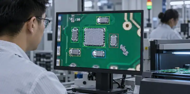
The image is often more informative than a reject code. A small deposit caused by incomplete aperture release may have a different outline from a deposit shifted partly outside its region of interest. Retain both the numerical result and its location so the process engineer can separate these possibilities.
Review the stencil aperture design when the same feature repeatedly fails while adjacent deposits remain stable. Changing the print recipe cannot correct every unsuitable opening, and modifying an aperture changes the reference against which future volume results should be interpreted.
Not every numerical exception has the same consequence. Fine-pitch adjacent leads, small passives and large thermal pads present different risks. Define critical deposits by package and function instead of asking the operator to treat every pad identically. That prioritization should sharpen the investigation, not create a blanket exemption for noncritical coordinates.
How do you read volume percentages correctly?
A volume percentage only becomes useful when its denominator is stated. Two reports can assign different percentages to the same physical deposit if they use different nominal geometry.
Identify the reference volume
Koh Young describes transfer efficiency as measured paste volume divided by stencil-aperture volume, multiplied by 100%. Confirm whether the report uses that convention or a different programmed nominal. Ask whether step-stencil thickness, aperture reductions, rounded corners and segmented openings are represented correctly.
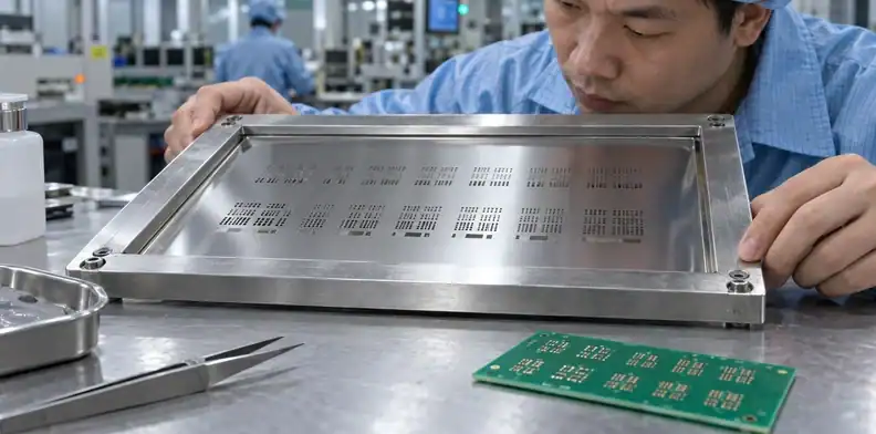
The copper land is not automatically the stencil opening. A deliberately reduced aperture can make a correct deposit look deficient if the program compares it with an unreduced pad-based volume. Conversely, an incorrect nominal can make excessive material appear acceptable. Geometry from the released stencil should therefore accompany the reported percentage.
Work through an aperture-volume example
Consider an illustrative rectangular opening measuring 0.40 × 0.20 mm through a 0.10 mm stencil. Its geometric volume is 0.0080 mm³. A measured deposit of 0.0064 mm³ corresponds to 80% transfer efficiency under that definition.
| Reference used for the same measured deposit | Nominal volume | Reported percentage |
|---|---|---|
| Actual 0.40 × 0.20 × 0.10 mm opening | 0.0080 mm³ | 80.0% |
| Assumed 0.50 × 0.25 × 0.10 mm pad-based prism | 0.0125 mm³ | 51.2% |
These numbers illustrate arithmetic, not an acceptance window. Real rounded or shaped apertures need their actual area, and multiple openings should not be replaced by one bounding rectangle. Before discussing a low percentage with a supplier, check the denominator; otherwise the proposed corrective action may target a calculation error rather than the deposit.
What makes an inspection program trustworthy?
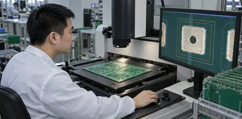
A trustworthy recipe uses the released board and stencil geometry, registers the panel correctly and can identify each result by side and location. Reusing a program by product name alone is not sufficient when artwork or apertures have changed.
The setup review should connect the board revision, stencil revision, panel arrangement and paste data to one approved program. A panel rotation, step-and-repeat change or underside image can require a different coordinate transformation. Confirm these transformations on an actual first print, not only on an imported CAD preview.
Alignment marks are another potential source of error. The PCB fiducial requirements explain their separate placement role. For paste inspection, verify that the selected marks are visible, correctly recognized and consistent with the program’s board reference.
Include representative small, large and unusual deposits in the setup check. The operator should be able to display their region boundaries, nominal values and measured surface. A single attractive screenshot of an easy pad does not demonstrate coverage of the features most likely to fail.
Record who can change the recipe and how those changes are reviewed. If an operator widens a limit to keep production moving, subsequent pass results are no longer comparable with the original setup unless the change is documented. Program approval should make that difference visible before a lot report is used as evidence of printing control.
How should paste limits be qualified?
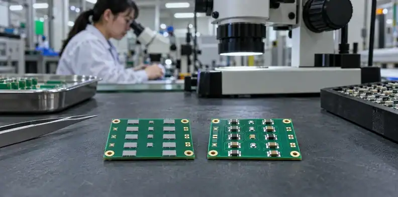
Qualify limits using the intended deposits, material and assembled-joint results. A workable volume range depends on the stencil, package and paste formulation being qualified.
Separate measurement settings from acceptance limits
Measurement settings determine which surface becomes part of the calculation; acceptance limits determine whether the resulting measurement passes. Altering a height threshold can change reported volume without changing the physical print. It should not be presented as a process improvement.
Indium’s published SiP printing discussion describes how changing threshold height affected SPI volume readings with thin stencils. The engineering lesson is to stabilize the measurement definition before comparing data or adjusting product limits. Preserve the previous settings and check representative deposits whenever the measurement recipe changes.
Correlate critical deposits with assembled joints
Use a controlled print-and-assembly trial to establish a workable range for the affected feature. Record the deposit, component placement and resulting joint under the agreed inspection and test plan. A range that removes SPI alarms but increases bridges, opens or inadequate joints is not an improvement.
Packages with hidden joints may require additional evidence. Discuss the relevant inspection scope with the BGA assembly team when the build includes such packages, without assuming X-ray will answer every joint question.
The trial should also show why the selected limits are meaningful near their boundaries. A process operating comfortably in the middle of a range does not establish that both extremes are safe. Keep any numerical limits tied to the qualified product and recipe rather than copying them into unrelated assemblies.
What causes false calls and missed defects?
False calls occur when the system rejects an acceptable print; missed defects occur when a problematic print escapes detection. Both need review, because simply reducing the reject count can hide a loss of inspection sensitivity.
| Suspected inspection problem | Check before changing limits | Evidence of a useful correction |
|---|---|---|
| Board-plane error | Local height reference and board support | Stable readings on unchanged deposits |
| Registration mismatch | Fiducial recognition and coordinate overlay | Regions follow the intended features |
| Stray paste outside the region | Inspection boundaries and gap coverage | Relevant unwanted deposit is detected |
| Reflection or surface interference | Raw images and measurement confidence | Repeatable result without a broad bypass |
| Borderline deposit dismissed as nuisance | Actual print and downstream joint | Product-specific disposition is justified |
Evaluate representative known conditions during setup, using approved reference samples or controlled trials. Do not deliberately place a defect into saleable production merely to test the machine. The purpose is to establish what the recipe recognizes, where it struggles and how uncertain calls reach engineering.
Compare reviewed false calls with the original reject images. If an engineer excludes a region, the excluded feature and reason should remain visible in the recipe history. An inspection report that omits inconvenient coordinates can look better while providing less protection.
Trend results by feature rather than relying only on one overall pass percentage. A repeated exception at a critical connector may be obscured by thousands of uneventful deposits elsewhere. For purchasing, a short feature-level explanation is more useful than an unexplained improvement in the machine’s dashboard summary.
How should a failed print be contained?
Stop the rejected board before placement on the inspected side and assign a documented recovery route. Cleaning and reprinting are possible only when the board, paste and cleaning process allow them; the machine reject is not automatic permission to wipe and retry.
Recover the board before placement
Preserve the failed-print image, coordinate and recipe version first. The recovery instruction should specify the approved method for removing paste, controlling residues and confirming that pads, holes and nearby features are clear. Protect the board finish and avoid transferring contamination to subsequent prints.
Check whether board reuse remains acceptable after the attempted recovery. A damaged finish, trapped material or excessive handling can make a second print unsuitable even if it later passes SPI. The separate PCB incoming inspection checks provide context for board condition, but do not qualify an assembly cleaning method.
Restart with a verified print
Correct the suspected setup or printing cause before restarting, then inspect the new deposit. Track elapsed time and paste handling against the current material instructions. Repeated trials should not create an undocumented mixture of fresh and aged material on the stencil.
If components are already placed on the rejected side, removal and recovery may need an approved rework process with additional inspection. If only the opposite side is populated, assess whether the cleaning and handling route protects that assembly. Record the side and actual recovery operation so the second-side print is not mistaken for work on a completely bare board.

Which records demonstrate printing control?
Useful SPI records connect measurements to the actual print, recipe and disposition. A pass certificate without the affected features or program identity cannot explain why a rejected panel was subsequently released.
| Record | Minimum useful detail | Decision it supports |
|---|---|---|
| Setup identification | Board, side, stencil and recipe revisions | Results belong to the released build |
| Deposit data | Units, nominal definition and feature coordinates | Percentages can be interpreted |
| Reject review | Image, observed condition and reviewer | False call or genuine print defect is distinguished |
| Recovery history | Cleaning/reprint route and new inspection | Rejected material did not progress unchecked |
| Qualification evidence | Relevant print-to-joint correlation | Limits have a product-specific basis |
Keep the original rejected-print record even when its replacement passes. The two records should share the board identity but retain separate timestamps, measurements and disposition. Replacing the first result with the later pass erases evidence of the interruption and prevents review of recurring recovery work.
Choose record depth according to the build’s risk and the agreed contract. Retaining every raw image indefinitely may not be necessary, while losing all evidence immediately after a critical reject leaves no way to review it. State which data are retained, how they are retrieved and what constitutes the lot summary.
Initial-build approval can connect these records to first article inspection versus AOI. First-article approval establishes a baseline; ongoing SPI data show whether later prints continue to follow that baseline. Request both when the distinction matters to your product.

What should your assembly RFQ specify?
Specify the SPI scope and expected evidence, not merely “SPI required.” The request for quotation (RFQ) should tell the assembler which build, side and features matter, while leaving equipment-specific settings to a justified process proposal.
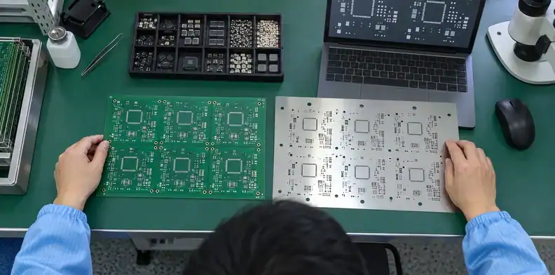
Provide the released assembly files, board and stencil information where available, critical package locations and any existing printing concerns. Identify whether you expect full inline coverage, initial-print checks or another agreed route. Include requirements for rejected-print containment, reinspection after recovery and recipe-change approval.
Ask the supplier to separate setup work from recurring inspection costs. A new aperture design, unfamiliar panel or narrow process window may require qualification effort that is not equivalent to running a repeat recipe. A quotation that explains these assumptions is easier to compare than one that lists the same inspection acronym without defining its work.
For an existing failure, send the original SPI image and measurements rather than only a photograph after reflow. Include the nominal-volume definition, stencil revision and the later joint condition, if known. This allows the review to distinguish an apparent reporting discrepancy from an actual deposition problem.
You can request a QueenEMS quotation for an SPI-controlled build with those files and the required inspection route. The package supports a proposal for printing qualification, inspection coverage and reject handling; it does not replace the product-specific acceptance decision your engineering and quality teams must make.
Sources
- Koh Young: why 3D solder paste inspection is needed.
- Indium: SiP printing and SPI measurement settings.
Written by the QueenEMS Engineering Team
Upload your files today · Free DFM check before production · Ship worldwide
Get your PCB prototypes in as fast as 24 hours. We handle FR4, Rogers, and hybrid boards up to 40 layers in volume production, with advanced builds subject to engineering review — free prototypes for 2–4 layer FR-4 boards, no minimum order.
Just upload your Gerber + BOM — we source every part, assemble, and inspect (AOI + X‑Ray) so you don't have to chase suppliers. Boards ship in as fast as 24 hours.