
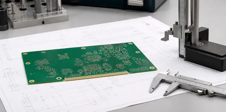
Quick Answer: PCB tolerance stack-up review connects the tolerances that affect the same mechanical or assembly fit. Instead of tightening every drawing note, buyers should identify the dimensions that share margin and decide which ones must be controlled.
PCB tolerance stack-up becomes an RFQ problem when separate drawing tolerances consume the same finished-board margin. Use this page when a drawing contains several tight dimensions that may be competing for the same manufacturing margin. The goal is to identify which features protect product fit and which tolerances can stay standard without harming assembly.
Table of Contents
- Why does tolerance stack-up change the RFQ?
- Which dimensions start the tolerance chain?
- How do thickness and hole tolerances interact?
- Where do outline, slot, and routed-edge limits collide?
- How can solder mask consume hidden tolerance?
- How should suppliers report a tolerance conflict?
- What table should buyers build before release?
- How should buyers package a tolerance-chain RFQ?
Why does tolerance stack-up change the RFQ?
PCB tolerance stack-up changes the RFQ because the finished board is judged by interacting limits, not by one isolated number. Finished thickness, plated hole size, slot width, outline location, copper weight, solder mask opening, and assembly clearance can all consume the same mechanical margin.
The existing PCB fabrication tolerances page explains which tolerances are worth paying for. This page goes one step later in the buying process: it asks whether the selected tolerances still work together in the product.
Buyer call: review the tolerance chain before asking suppliers to quote a stack of tight limits that may not improve fit or yield.
This review is most valuable when the product has a real mechanical interface: enclosure rails, press-fit connectors, board-to-board sockets, optical alignment, keyed slots, or a test fixture. In those cases, a single tight tolerance rarely protects the product by itself. The fit is protected by the chain of datum, feature, fabrication method, and inspection evidence.
A useful way to start is to choose the assembly condition that would fail first. If the enclosure fit is the real limit, outline and mounting holes matter most. If a connector is the limit, finished hole and board thickness may outrank cosmetic edge tolerance.
For early supplier screening, ask which tolerance is likely to drive cost before asking for a final number. The answer often reveals whether the supplier understands the product interface or is only quoting standard fabrication capability.
Which dimensions start the tolerance chain?
Start with the dimensions that locate the board in the product: outline, mounting holes, connectors, slots, edge contacts, and any datum used by the enclosure or assembly fixture. These features decide whether later tolerances matter.
For example, a tight connector slot may not help if the board outline datum is loose. A controlled press-fit hole may still fail if finished thickness, plating build, and drill registration are not reviewed together. The tolerance chain should follow the way the board is assembled, not the order of notes on the drawing.
| Tolerance-chain input | Why it can consume margin | RFQ action |
|---|---|---|
| Functional datum | Other dimensions reference this feature | Mark datum on drawing and assembly view |
| Finished thickness | Affects slots, press fit, standoffs, and fixtures | Quote nominal plus accepted range |
| Mask registration | Can reduce exposed pad or dam width | Tie mask note to critical component areas |
RFQ signal: mark the true datums and functional dimensions so the supplier knows which tolerances protect fit.
A good RFQ makes the functional datum visible. Suppliers can hold tighter dimensions when they understand what the dimension controls, but they cannot guess whether a hole is only for mounting or also used to locate a connector. Naming the datum prevents expensive precision from being applied to the wrong features.
Datum clarity is especially important when the board outline is generated from one CAD source and the mechanical drawing uses another. A small mismatch can make every downstream tolerance discussion confusing even when the supplier is capable.
Assembly context is not optional when tolerance chains involve connectors, LEDs, displays, housings, or test fixtures. The bare board supplier does not need every assembly drawing, but it needs enough information to understand which features locate the product.

How do thickness and hole tolerances interact?
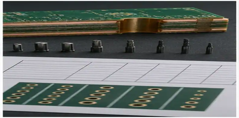
Finished thickness and hole tolerances interact whenever a component, fastener, connector, or fixture depends on both. Thick boards can change drill aspect ratio, plating behavior, press-fit mechanics, and slot routing limits.
Use PCB board thickness selection for the thickness decision itself and press-fit hole tolerance review for connector fit. In this RFQ review, the buyer should check whether those decisions point to the same manufacturing evidence.
Acceptance rule: do not quote a press-fit, connector, or mechanical slot only from nominal CAD dimensions.
Thickness deserves special attention because it is both an electrical and mechanical variable. The same thickness change can move impedance, press-fit retention, connector seating, and enclosure clearance. Treat thickness changes as engineering decisions when they affect more than shipping paperwork.
For holes and thickness, ask whether the quoted tolerance is measured before or after surface finish, plating, or final inspection. Finished-board language prevents arguments about a process value that does not match the buyer’s acceptance point.
Use example values only as review triggers, then replace them with the real drawing limits. A common RFQ discussion might compare a 1.60 mm finished thickness callout, a ±0.10 mm board-thickness window, a 0.80 mm routed slot, a ±0.05 mm functional slot tolerance, and a 0.10 mm solder-mask dam near fine-pitch pads. Those numbers are not universal QueenEMS limits; they are the type of dimensions that should be checked together before a supplier quotes the build.
Some tolerance conflicts come from copied legacy notes. A drawing may carry a tight outline requirement because an older enclosure needed it, while the current board only needs a few mounting holes controlled. Remove legacy precision when it no longer protects function.
Where do outline, slot, and routed-edge limits collide?
Outline, slot, and routed-edge limits collide when the board edge is also a functional interface. Edge connectors, castellated features, keyed slots, constrained enclosure walls, and fixture rails can all make routing tolerance a yield issue.
A useful drawing identifies which edges are cosmetic, which are mechanical datums, and which are clearance-only. That lets the supplier quote realistic tooling and inspection instead of applying one blanket tolerance everywhere.
Buyer call: use PCB outline tolerance requirements for edge-specific rules, then bring the critical edges into the full tolerance stack-up review.
Routed-edge limits often hide in drawing notes copied from older projects. A tight outline tolerance may be justified for one edge and unnecessary for another. Splitting functional edges from clearance edges can reduce cost while keeping the product fit protected.
Slot and edge tolerances should also state whether burrs, glass fibers, or exposed copper are cosmetic or functional issues. A tight dimensional tolerance does not automatically define the edge quality needed for the product.
Inspection method should be named for the most critical features. A supplier may inspect routing, drilling, and mask with different tools, so the buyer should know which report or measurement supports acceptance.
How can solder mask consume hidden tolerance?
Solder mask consumes tolerance when pad exposure, mask registration, dam width, and component pitch have little room for shift. The copper may be correct while the assembly still sees exposed copper, reduced solderable area, or mask encroachment.
Do not treat solder mask as a cosmetic layer on dense boards. Pair the mask opening note with the footprint, finish, component pitch, and inspection need. The solder mask opening requirements page owns the mask details; the stack-up view checks whether mask tolerance fits the assembly margin.
| Supplier conflict note | Likely root cause | Buyer response |
|---|---|---|
| Hole and outline datum conflict | Mechanical drawing and fabrication data disagree | Freeze the datum before quote release |
| Slot tolerance drives routing cost | Functional slot is tighter than surrounding edge | Tighten only the interface slot |
| Mask tolerance blocks fine pitch | Pad pitch leaves no process window | Review footprint, mask opening, and finish together |
Proof rule: ask whether solder mask registration is being judged against the critical component features, not only against a generic fabrication note.
Solder mask tolerance is easy to miss because many drawings treat mask as a standard note. On fine-pitch parts, however, mask registration can consume the same soldering margin that pad size and finish thickness are trying to protect. Review mask, copper pad, finish, and component pitch together.
Mask-sensitive features deserve their own line in the RFQ table. A QFN thermal pad, fine-pitch BGA escape, or test pad array may need a different mask expectation from the rest of the board, and that exception should not be buried in generic notes.
Tolerance stack-up review also protects quote comparison. One supplier may include special inspection, another may quote standard tolerance, and a third may assume engineering will relax a feature later. Those quotes are not equivalent.
How should suppliers report a tolerance conflict?
A supplier should report a tolerance conflict by naming the exact feature, the conflicting notes, the likely manufacturing limit, and the proposed alternative. A vague ‘tolerance too tight’ answer does not help purchasing compare quotes.
Good responses show whether the conflict affects cost, lead time, special tooling, inspection method, yield, or assembly fit. They also identify whether the buyer can loosen a nonfunctional tolerance while protecting the true critical dimension.
RFQ signal: a useful supplier answer returns a decision, not just a complaint.
Supplier conflict notes should be answered with a decision, not a general request to ‘do your best.’ The buyer can loosen a nonfunctional tolerance, change the datum, approve special inspection, or redesign the interface. Each answer has different cost and schedule impact.
When a supplier reports a conflict, ask for the lowest-impact relaxation first. Sometimes one nonfunctional decimal-place tolerance is driving cost while the true functional feature can remain controlled. This keeps the conversation tied to yield rather than blame.
When time is short, focus on the three features most likely to stop assembly. That usually gives a better result than asking the supplier to review every note on a dense mechanical drawing.

What table should buyers build before release?
Build a tolerance stack-up table that connects each critical feature to its datum, functional reason, current tolerance, supplier concern, and approval owner. The table can be short; the value is that it forces separate notes to be reviewed as one system.
Do not put every drawing dimension into the table. Include only dimensions that can stop fit, assembly, test, shipment, or customer acceptance. That keeps the RFQ practical and helps the supplier quote what matters.
Release rule: the tolerance table should show what may be relaxed and what cannot move without engineering approval.
The table should be short enough for purchasing to use. A five-row tolerance chain is better than a fifty-row drawing export because it forces the team to identify what actually controls fit. Keep background dimensions on the drawing and put only decision-driving features into the RFQ table.
The table should show the buyer’s priority order. Suppliers can often propose a workable trade-off when they know whether fit, cost, lead time, inspection evidence, or cosmetic appearance is the dominant constraint.
A clean RFQ states what can move. If a noncritical edge or slot can accept a wider tolerance, say that early so the supplier does not price unnecessary precision.
How should buyers package a tolerance-chain RFQ?
Use this review when the same board has finished thickness, hole, slot, outline, solder mask, and connector-location limits that all affect the same fit. The package should include the fabrication drawing, Gerber or ODB++, assembly drawing if fit matters, a short critical-dimension table, component interface notes, and the buyer’s priority order.
Buyer call: quote the finished board, not a disconnected list of nominal features.
Use the QueenEMS contact page to submit the tolerance package for RFQ review. QueenEMS can return the practical split between dimensions that are manufacturable as written, limits that will drive cost or inspection time, features that need assembly context, and tolerances that should be relaxed before supplier comparison.
FAQ
Is PCB tolerance stack-up only a mechanical issue?
No. It can also affect assembly yield, solder mask exposure, connector fit, electrical spacing, and inspection evidence.
Should every tolerance be tightened for quality?
No. Tighten only the dimensions that protect fit, function, safety, or customer acceptance.
Can suppliers decide which tolerances matter?
They can flag manufacturing risk, but engineering should own the final functional priority.
A useful tolerance review also states what evidence will close the issue. That might be a dimensional inspection report for a datum feature, a finished-thickness record for a connector zone, a routed-slot measurement, or a mask registration check near fine-pitch pads. Naming the evidence prevents the supplier from quoting a difficult feature without a matching inspection plan.
One more useful check is the inspection burden behind the tolerance. A supplier may be able to meet a number but need added measurement time, fixture setup, or first-article inspection to prove it. The buyer should decide whether that evidence is worth the cost before the quote is released, especially when the tight feature protects only a legacy assumption.
The quotation should also separate capability from acceptance. A supplier may say a tight feature is buildable, but the buyer still needs to know whether the tolerance is inspected on every lot, sampled during first article, or controlled only by normal process capability. That distinction matters when the feature controls a connector, fixture, or enclosure wall. Without it, the buyer may pay for a tolerance that is not backed by the evidence needed at receiving.
Written by the QueenEMS Engineering Team
Upload your files today · Free DFM check before production · Ship worldwide
Get your PCB prototypes in as fast as 24 hours. We handle FR4, Rogers, and hybrid boards up to 40 layers in volume production, with advanced builds subject to engineering review — free prototypes for 2–4 layer FR-4 boards, no minimum order.
Just upload your Gerber + BOM — we source every part, assemble, and inspect (AOI + X‑Ray) so you don't have to chase suppliers. Boards ship in as fast as 24 hours.