
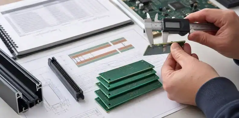
Quick Answer: A nominal 1.6 mm (about 63 mil) is a common starting point for a rigid FR-4 PCB, not a universal requirement. Choose PCB thickness from connector and enclosure fit first, then confirm stackup, stiffness, assembly handling, and finished-thickness tolerance. The chart below converts common nominal sizes; actual availability and measurement rules must be confirmed with the fabricator.
Key takeaways
- Do not choose board thickness only from habit; connect it to the enclosure, connector, stackup, and assembly process.
- A commonly available thickness can reduce cost and lead-time risk, but it still must fit the design.
- Non-standard thickness should be named in the drawing and quoted before fabrication starts.
- Thickness tolerance matters when edge connectors, press-fit parts, rails, or mechanical stacking control the fit.
A buyer may ask whether a PCB should be 1.0 mm or 1.6 mm. There is no universal answer. The release decision has to connect thickness to product fit, manufacturability, and quotation assumptions.
Table of Contents
- PCB thickness chart (mm and mils)
- Choose PCB thickness from the tightest fit constraint
- When a standard PCB thickness is enough
- Check stiffness, panel handling, and assembly risk
- Connect thickness to stackup and impedance
- Watch enclosure, weight, and thermal tradeoffs
- Specify PCB thickness tolerance where fit is controlled
- Send QueenEMS the thickness decision package
PCB thickness chart: common sizes in mm and mils
The values below are unit conversions and selection prompts for rigid boards, not a promise that every material, layer count, copper weight, or tolerance is available at each size. One mil is 0.0254 mm. In particular, 1.6 mm is about 63 mil; 0.062 in is about 1.575 mm, so do not silently treat those numbers as identical on a fit-critical drawing.
| Nominal thickness | Approx. inches / mils | What to verify before release |
|---|---|---|
| 0.8 mm | 0.0315 in / 31.5 mil | Enclosure clearance, unsupported span, SMT panel support |
| 1.0 mm | 0.0394 in / 39.4 mil | Connector fit, board stiffness, and stackup availability |
| 1.2 mm | 0.0472 in / 47.2 mil | Connector fit, layer count, and supplier tolerance |
| 1.6 mm | 0.0630 in / 63.0 mil | Common rigid FR-4 starting point; still check fit and stackup |
| 2.0 mm | 0.0787 in / 78.7 mil | Connector clearance, drilling, and assembly handling |
| 2.4 mm | 0.0945 in / 94.5 mil | Fabricator capability, hole aspect ratio, and finished tolerance |
If a connector or slot controls fit, use its drawing to specify the allowable finished-thickness range, not just the nearest number in this chart. If electrical performance controls the decision, review the proposed layer stack with the fabricator before changing overall thickness.
Choose PCB thickness from the tightest fit constraint
PCB thickness should start with the physical part that has the tightest fit requirement. Edge connectors, card guides, board-to-board connectors, press-fit hardware, enclosure slots, heatsinks, and mechanical standoffs can all make thickness a functional requirement.
If no part controls the thickness, 1.6 mm FR4 is often a safe commercial default for many rigid boards. But a default becomes risky when the product has a card-edge slot designed for a narrower board, a thin handheld enclosure, or a connector stack height that leaves little room.
Engineering should identify the mechanical constraint before purchasing sends the RFQ. The board thickness in the quote should match the drawing and assembly model. If a supplier assumes 1.6 mm while the product needs 1.0 mm, the quote comparison is already distorted.
A practical RFQ instruction is: “Quote a nominal 1.0 mm finished PCB thickness and state the achievable tolerance. Flag any effect on stackup, impedance, or panel handling before fabrication release.” This keeps the decision tied to the delivered board rather than laminate inventory alone.
| Fit driver | Thickness impact | Buyer check |
|---|---|---|
| Card-edge connector | Slot fit may be strict | Finished thickness tolerance |
| Enclosure groove | Board must slide or clamp | CAD/mechanical drawing |
| Press-fit hardware | Hole and board strength interact | Supplier capability |
| Thin handheld product | Space and weight limit | Stiffness review |
For startup builds, the first mistake is often copying prototype thickness into production without checking the final housing. A bench prototype can work at 1.6 mm while the production enclosure needs 1.0 mm, or a thin prototype can pass bring-up while the production assembly needs more stiffness for shipping and connector insertion.
Purchasing should ask engineering why the thickness was chosen. If it is only a preferred starting point, a fabricator may suggest another available construction. If a connector, slot, or controlled stackup fixes the dimension, engineering should approve any substitution before release.
When a standard PCB thickness is enough
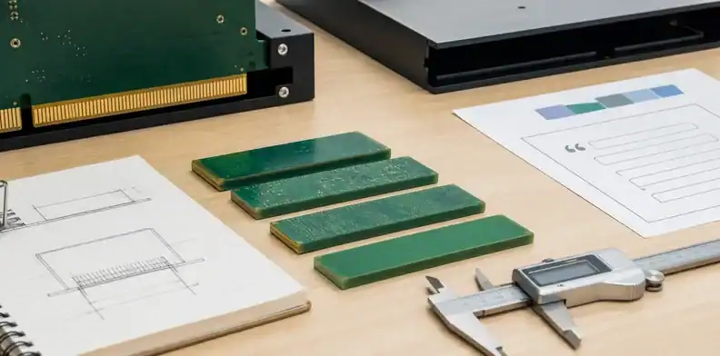
Standard thickness options usually reduce price and quotation risk because suppliers build them often. Common rigid FR4 choices include 0.8 mm, 1.0 mm, 1.2 mm, 1.6 mm, 2.0 mm, and 2.4 mm, though exact availability depends on layer count, material, copper weight, and supplier process.
Do not assume every supplier uses the same standard thickness list. A construction that is routine for a two-layer board may not be routine for an eight-layer impedance-controlled stackup. Material availability, copper weight, layer count, and panel size can change the options.
When thickness is flexible, ask suppliers to quote the closest standard option and state the tolerance. That can save cost without compromising the product. When thickness is fixed, make it clear that substitutions require engineering approval.
This decision often sits beside layer-count planning. The 2-layer vs 4-layer PCB article helps with electrical and routing decisions, while this article focuses on finished thickness and mechanical fit.
A useful quote comparison keeps thickness, layer count, material, and tolerance in the same line. If Supplier A quotes 1.6 mm and Supplier B quotes 1.2 mm, the lower price may come from a different construction rather than better purchasing. The buyer should ask both suppliers to quote the same finished thickness before deciding.
Standard thickness also affects lead time. A common construction may move faster because laminate and prepreg combinations are already familiar to the shop. A less common thickness may still be easy for one supplier and slow for another, so the RFQ should ask for any lead-time effect rather than assuming all options are equal. Buyer call: Use standard thickness to control cost only when the product has no connector, enclosure, stiffness, or stackup reason to require a different value.
Check stiffness, panel handling, and assembly risk
Thin boards can reduce size and weight, but they can flex during SMT, depaneling, connector insertion, or final use. Thick boards can improve stiffness but may raise drilling, plating, material, or assembly challenges.
A buyer should ask whether the board will run through SMT in a panel, whether heavy components are present, whether there are large cutouts, and whether the assembly needs support tooling. These details affect yield and handling, not only bare-board price.
Small boards may tolerate thinner material because the unsupported span is short. Large boards with BGA packages, connectors, or heavy inductors may need stiffness to avoid warpage and solder-joint stress. The supplier and assembler should both see the thickness expectation before quotation.
Panel strategy also matters. A thin PCB may need stronger rails or a different panel design for assembly. A thick PCB may need different depaneling, routing, or scoring decisions. Thickness should therefore be reviewed with the production route, not only the bare board.
For assembly planning, connect thickness to PCB panelization for SMT. Panel handling can turn a theoretically good thickness into a production problem.
For PCBA, thickness also affects fixtures, conveyors, support pins, and depaneling stress. A very thin panel may need carrier support during stencil printing and reflow. A very thick board may need routing rather than scoring if the edge must stay clean. These assembly costs should be visible before the buyer selects a bare-board thickness only from the PCB quote. Assembly signal: A thickness choice is not ready for release until the bare-board supplier and assembler can both build and handle it safely.
Connect thickness to stackup and impedance
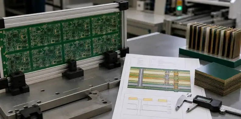
Board thickness is part of the stackup. Changing it can change dielectric spacing, controlled impedance, copper balance, warp risk, and layer-to-layer construction. A buyer should not let purchasing approve a thickness change without engineering review.
For simple two-layer boards, a small thickness change may be mostly mechanical. For multilayer or high-speed boards, it can affect impedance, return paths, and manufacturability. The stackup and thickness should therefore be approved together.
If the supplier proposes a different thickness to reduce cost or improve availability, ask whether the stackup, impedance, and drill aspect ratio still meet the design requirement. A lower price is not useful if the board no longer matches the released design.
The PCB stack-up design article explains layer construction in more depth. At RFQ stage, the buyer’s job is to keep finished thickness, stackup revision, and quote assumptions aligned.
| Change request | What it can affect | Approval owner |
|---|---|---|
| 1.6 mm to 1.2 mm | Stiffness, impedance, enclosure | Engineering |
| Copper weight increase | Press thickness and drilling | Engineering and supplier |
| Material change | Dielectric and availability | Engineering |
| Layer count change | Stackup and finished thickness | Engineering |
The board thickness also changes how drill aspect ratio is viewed. A very thick board with small plated holes may push plating difficulty higher, while a thinner board may relax that part of the process. If the design has small vias, high copper, or press-fit holes, the supplier should confirm that the proposed thickness still fits their fabrication window.
This is why the thickness decision should not be hidden in a purchasing note. It belongs with the stackup and fabrication drawing, where CAM can see it before process planning begins. Stackup rule: Treat a thickness change on controlled or multilayer boards as a stackup change until engineering approves otherwise.
Watch enclosure, weight, and thermal tradeoffs
Thickness also affects product feel, weight, screw loading, board deflection, and thermal path. These issues may not appear in a bare-board quote but can show up during final assembly or field use.
A thin board may help a compact product meet enclosure limits, but it may need support around connectors or batteries. A thicker board may feel stronger, but it can clash with standoffs, displays, or mechanical stack height. The buyer should check the mechanical drawing before accepting a supplier substitution.
Thermal behavior can also be part of the decision. Standard FR4 thickness changes do not replace thermal design, but copper weight, metal-core choices, vias, and component placement can interact with board thickness. If heat is the real concern, the RFQ should not solve it only by guessing a thicker FR4 core.
State the design reason in the release package: “1.0 mm for the enclosure slot” or “1.6 mm for connector support and stiffness” is more useful than simply writing “standard thickness.”
Thermal requirements should be handled with the right design control. If heat spreading is the main problem, copper area, thermal vias, metal-core construction, component placement, airflow, or heatsink contact may matter more than a small change in FR4 thickness. The buyer should ask engineering what the thermal path is before accepting a supplier’s thicker-board suggestion as the fix. Decision point: Thickness should support the product’s mechanical and thermal intent, not hide an unresolved enclosure or heat problem.
Specify PCB thickness tolerance where fit is controlled
Finished thickness tolerance matters when the board must fit a slot, connector, rail, housing, or press-fit system. A nominal value without tolerance can still create receiving disputes.
Suppliers may quote different finished thickness tolerances depending on material, copper, layer count, and process. The buyer should ask for the tolerance in the quote and decide whether the product can accept it. Tighter tolerance can raise cost or limit supplier options.
A drawing note should say whether the nominal value is finished thickness and whether copper, finish, or solder mask is included in the controlled dimension. This matters for edge connectors and mechanical fit.
Connector drawing example: calculate the acceptable finished thickness
The connector drawing, not a generic “standard board thickness,” defines the fit. For example, Molex’s EXTreme PowerEdge Plus product page specifies a mating PCB thickness of 1.57 ± 0.13 mm: an arithmetic range of 1.44–1.70 mm. The Samtec HTEC8 drawing identifies its -01 option as a 1.57 mm card and gives the mating edge-card thickness tolerance as ± 0.157 mm, measured pad to pad. That gives 1.413–1.727 mm for that option. These are requirements for two specific connector products, not a universal PCB fabrication tolerance.
As a calculation example only, a hypothetical quote for 1.60 ± 0.15 mm finished thickness permits 1.45–1.75 mm. Its upper limit exceeds both connector examples, despite the familiar 1.6 mm nominal value. This comparison is valid only when the quoted dimension and connector requirement use the same measurement location and surface definition; it is not a statement of QueenEMS manufacturing capability.
For a real build, record the exact connector part number and drawing revision. Put the required minimum, maximum, and measurement location on the PCB drawing and RFQ; ask the fabricator to confirm the achievable finished range for the proposed stackup. Receiving inspection should measure the mating edge using that same definition. Recheck the limits if the connector changes rather than copying either example range into another design.
If thickness tolerance is one of several dimensional concerns, pair it with PCB fabrication tolerances. The goal is to spend tolerance budget where the product truly needs it.
| Fit condition | Tolerance question | Buyer action |
|---|---|---|
| Card edge | Finished board thickness? | Confirm connector spec |
| Enclosure slot | Maximum and minimum fit? | Check mechanical drawing |
| Press-fit hardware | Board strength and hole plating? | Ask supplier before release |
| General mounting | Loose tolerance acceptable? | Avoid over-control |
A final practical check is whether the thickness note appears in all release documents. The drawing, stackup, quote, PO, and assembly build package should not show different values. If the CAD export says one number and the PO says another, the supplier may build exactly what one file asked for while the product owner expected something else.
Receiving should also know which measurement matters. For many boards, nominal finished thickness is enough. For edge connectors and controlled mechanical slots, the receiving team may need a caliper check and an accepted tolerance before the boards are released to assembly. Tolerance rule: Tighten PCB thickness tolerance only where the product fit or assembly process actually depends on it.
Send QueenEMS the thickness decision package
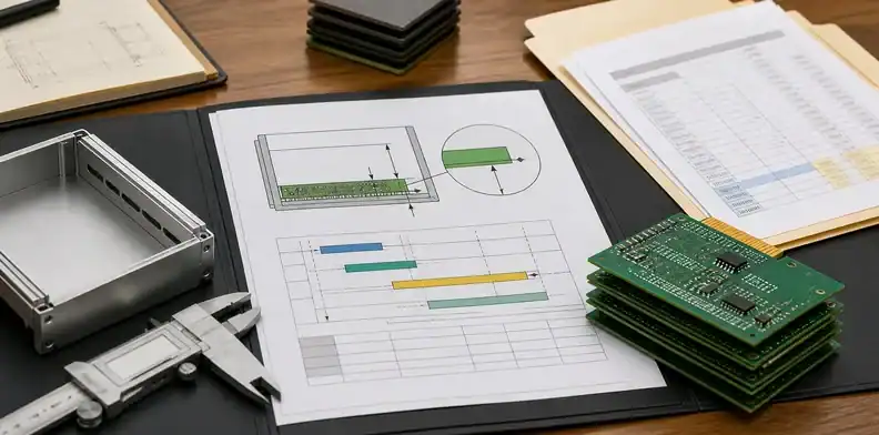
Send the mechanical drawing, enclosure or connector requirement, PCB files, layer count, stackup target, copper weight, controlled impedance needs, assembly plan, and target quantity. QueenEMS can review whether the requested thickness is quote-ready and whether any supplier substitution needs engineering approval.
For PCB work, the useful output is a finished-thickness note, tolerance boundary, and stackup question list. For PCBA work, the review also checks panel handling, connector fit, SMT support, and whether a thinner or thicker board creates assembly risk.
If your PCB or PCBA project needs the board thickness checked before quotation or production release, contact QueenEMS with the mechanical constraints, stackup, files, and order quantity so our team can help turn the thickness choice into a manufacturable quote package.
FAQ
Is 1.6 mm always the best PCB thickness?
No. It is a common default for many rigid FR4 boards, but the best choice depends on connector fit, enclosure clearance, stiffness, stackup, impedance, and cost.
Can I change from 1.6 mm to 1.0 mm to save space?
Yes, if engineering confirms the enclosure, stiffness, impedance, panel handling, and assembly process still work. The supplier should quote the change before fabrication starts.
Does PCB thickness affect controlled impedance?
Often yes on multilayer or controlled-impedance boards. Thickness changes can alter dielectric spacing and stackup, so engineering should approve the revised construction.
What should QueenEMS check before quoting board thickness?
QueenEMS should review the mechanical fit, finished thickness tolerance, stackup, copper weight, layer count, connector needs, panel handling, and production quantity.
Sources
- Altium: Standard PCB Thickness and Your Layer Stack explains how overall thickness interacts with the layer stack. The chart above uses arithmetic conversion; quoted sizes and tolerances remain supplier-specific.
Written by the QueenEMS Engineering Team
Upload your files today · Free DFM check before production · Ship worldwide
Get your PCB prototypes in as fast as 24 hours. We handle FR4, Rogers, and Flex up to 60 layers — free prototypes for 2–4 layer boards, no minimum order.
Just upload your Gerber + BOM — we source every part, assemble, and inspect (AOI + X‑Ray) so you don't have to chase suppliers. Boards ship in as fast as 24 hours.