

Quick Answer: Decision: finished-outline tolerance review. Controlled object: dimensioned profile drawing with X/Y datums, routed slots, cutouts, corner radii, tabs, and measurement locations. Design-owned boundary: mating dimensions, datum scheme, slot size, connector-edge relationship, and any locally tighter fit window. Supplier discretion: supplier-standard profiling compensation outside the controlled fit dimensions and cosmetic non-mating edges. Stop rule: conflicting board outlines, an undimensioned mechanical cutout, or a tolerance that the chosen profile process cannot demonstrate.
Outline tolerance RFQ path
- What does outline tolerance decide before quote?
- Which files should control the board outline?
- How do routing and V-score change the tolerance risk?
- Where do fit problems usually appear?
- How should buyers answer outline DFM questions?
- What should the outline RFQ package include?
What does outline tolerance decide before quote?
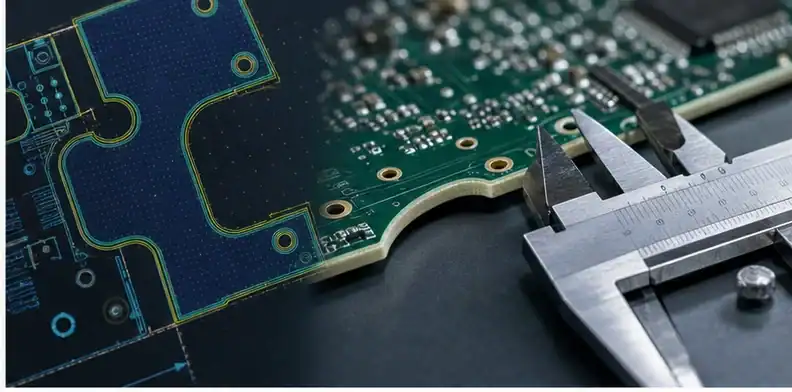
PCB board outline tolerance requirements decide whether the finished board will fit the enclosure, mate with connectors, align to mounting hardware, and survive depaneling without a late mechanical dispute. Treat the outline as a controlled manufacturing feature, not as a line that the factory can interpret freely.
- The RFQ should identify the controlled outline layer and the features that drive fit.
- Internal cutouts, connector windows, notches, and tabs deserve more review than a simple rectangle.
- A supplier response should separate standard routing tolerance from special mechanical acceptance.
| Buyer concern | RFQ decision |
|---|---|
| Enclosure fit | Define finished outline and cutout tolerance |
| Connector exposure | Call out the functional edge or window |
| Prototype only | Accept normal tolerance only when fit risk is low |
Bottom line: Outline tolerance belongs in the quote when the board shape can decide fit, assembly, or acceptance.
Which files should control the board outline?
The board outline should be controlled by a clear mechanical layer, fabrication drawing, or ODB++/IPC-2581 data set that agrees with the Gerbers. A screenshot or CAD preview is not enough for a production quote because CAM must know which contour is the finished routed edge.
- Send the mechanical layer that contains the complete closed outline.
- Match drawing dimensions to the same released revision as the Gerber package.
- Name the layer plainly so CAM does not confuse keepouts, milling paths, and notes.
| File | What it proves |
|---|---|
| Mechanical outline Gerber | Finished board contour and cutouts |
| PDF fabrication drawing | Tolerance, datums, and controlled dimensions |
| Readme or release note | Which file revision is active |
Bottom line: One controlled outline source prevents the supplier from quoting a shape the buyer did not intend.
How do routing and V-score change the tolerance risk?
Routing and V-score do not create the same edge condition. Routed outlines can control complex curves and cutouts, while V-score is efficient for straight-line separation but can leave a different edge accuracy and stress profile. The quote should say which method is allowed for each edge.
- Do not let a panelization choice quietly change a controlled mechanical edge.
- Separate outside contour tolerance from cutout, slot, and tab-removal expectations.
- Ask whether the final edge is measured after depaneling when fit is tight.
| Edge method | Buyer review point |
|---|---|
| CNC routing | Tool radius, burrs, and local tolerance |
| V-score | Straight-line constraint and break edge condition |
| Mouse bite tabs | Tab residue near functional edges |
Bottom line: The accepted profiling method is part of the outline requirement, not a factory detail.
Where do fit problems usually appear?
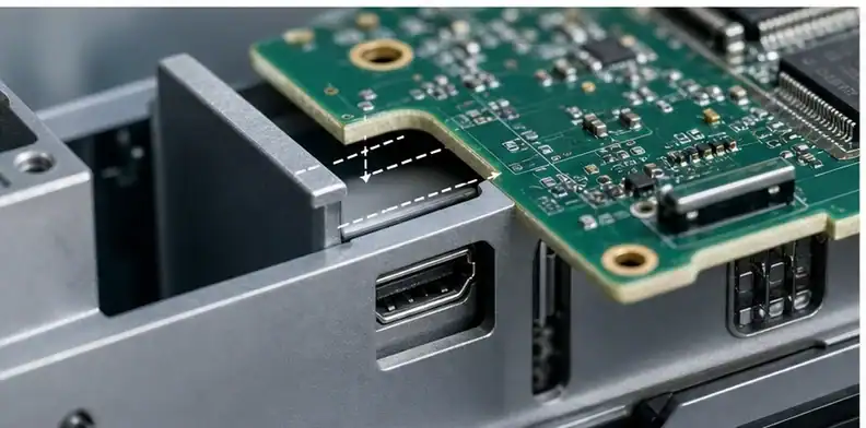
Fit problems usually appear at connector windows, mounting-hole relationships, enclosure walls, keepout edges, and internal cutouts that guide another part. These locations should be named in the RFQ so the supplier knows which dimensions are functional and which are normal board-outline features.
- Use datums when a hole-to-edge or connector-to-edge relationship controls assembly.
- Call out inside corners when router radius affects the mating part.
- Review the panel plan when edge components or tabs sit near a functional shape.
| Feature | Why it needs attention |
|---|---|
| Connector window | Controls product fit and user access |
| Mounting-hole pattern | Controls screw alignment and enclosure stress |
| Internal cutout | Can fail because of router radius or tolerance stack-up |
Bottom line: A supplier cannot protect a critical outline dimension unless the RFQ identifies it.
How should buyers answer outline DFM questions?
Outline DFM questions should be answered with the mechanical function in mind. A request to change a notch, radius, tab location, or route path may be harmless on one edge and unacceptable on another, so the buyer should approve the change against the enclosure or assembly requirement.
- Ask for a marked view when CAM proposes an outline adjustment.
- Do not approve route simplification before checking connector and enclosure fit.
- Keep the final outline decision with the released quote file set.
| DFM request | Approval check |
|---|---|
| Increase inside radius | Verify mating feature still clears |
| Move breakaway tab | Confirm no residue remains on a controlled edge |
| Simplify contour | Check product fit before cost approval |
Bottom line: Mechanical intent should decide whether an outline DFM change is acceptable.
What should the outline RFQ package include?
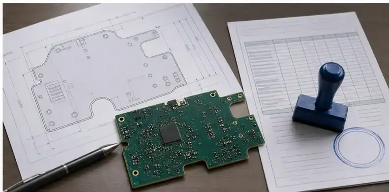
A clean outline RFQ includes the controlled outline layer, fabrication drawing, finished thickness, profiling method, critical dimensions, acceptable burr or tab residue condition, revision record, and evidence request. That package lets QueenEMS compare the real mechanical requirement instead of pricing a vague shape.
- Mark the dimensions that affect fit rather than over-controlling every edge.
- State whether prototype measurements, first-article checks, or photos are needed.
- Include enclosure or mating-part context when the board shape is not self-explanatory.
| RFQ item | Include when |
|---|---|
| Mechanical drawing | Any fit dimension is controlled |
| Panel requirement | Edge quality changes after depaneling |
| Inspection evidence | The customer will reject out-of-fit boards |
Bottom line: The RFQ should make the finished outline measurable and commercially comparable.
What should the buyer record before release?
Production record for the finished-outline tolerance review
Controlled object
Controlled object: dimensioned profile drawing with X/Y datums, routed slots, cutouts, corner radii, tabs, and measurement locations.
Failure boundary
Failure boundary: enclosure interference, connector misalignment, loose locating features, or a profile measured from the wrong datum.
Design-owned conditions
Design-owned conditions: mating dimensions, datum scheme, slot size, connector-edge relationship, and any locally tighter fit window.
Supplier discretion
Supplier discretion: supplier-standard profiling compensation outside the controlled fit dimensions and cosmetic non-mating edges.
Required proof
Required proof: first-article profile measurements taken from the named datums, with slot and cutout results reported separately.
Production stop
Production stop: conflicting board outlines, an undimensioned mechanical cutout, or a tolerance that the chosen profile process cannot demonstrate.
Repeat-order baseline
Repeat-order baseline: the signed profile drawing, measurement method, sampling plan, and approved enclosure or carrier reference.
RFQ inputs
RFQ inputs: mechanical drawing, authoritative outline layer, STEP data where useful, enclosure interface, panel format, quantity, and inspection plan.
FAQ
Can the supplier decide the finished-outline tolerance review?
Discretion for finished-outline tolerance review: supplier-standard profiling compensation outside the controlled fit dimensions and cosmetic non-mating edges. Engineering control for finished-outline tolerance review: mating dimensions, datum scheme, slot size, connector-edge relationship, and any locally tighter fit window.
What stops this finished-outline tolerance review?
Stop rule for finished-outline tolerance review: conflicting board outlines, an undimensioned mechanical cutout, or a tolerance that the chosen profile process cannot demonstrate. Disposition owner for finished-outline tolerance review: the named engineering approver.
Which proof closes the finished-outline tolerance review?
Evidence for finished-outline tolerance review: first-article profile measurements taken from the named datums, with slot and cutout results reported separately. Revision link for finished-outline tolerance review: the quoted dataset.
What survives into the next order?
Reorder baseline for finished-outline tolerance review: the signed profile drawing, measurement method, sampling plan, and approved enclosure or carrier reference.
For a focused finished-outline tolerance review, send QueenEMS mechanical drawing, authoritative outline layer, STEP data where useful, enclosure interface, panel format, quantity, and inspection plan. Redline request: finished-outline tolerance review. Open assumptions: finished-outline tolerance review. Approver: finished-outline tolerance review owner.
Written by the QueenEMS Engineering Team
Sources
Upload your files today · Free DFM check before production · Ship worldwide
Get your PCB prototypes in as fast as 24 hours. We handle FR4, Rogers, and Flex up to 60 layers — free prototypes for 2–4 layer boards, no minimum order.
Just upload your Gerber + BOM — we source every part, assemble, and inspect (AOI + X‑Ray) so you don't have to chase suppliers. Boards ship in as fast as 24 hours.