
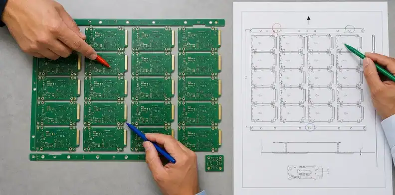
Quick Answer: PCB panel drawing approval is the formal check that the fabrication panel can run through assembly and depaneling without changing the board design. Approve the exact drawing revision only after the fabricator, assembler, and buyer agree on rails, fiducials, tooling holes, board orientation, routing or V-score geometry, X-outs, coupons, and marking.
A panel can be manufacturable for bare-board fabrication and still be awkward for solder paste printing, pick-and-place, selective soldering, test, or final separation. That is why this review copy expands the existing QueenEMS panelization article from “how panelization affects yield and cost” into a buyer-controlled approval workflow.
This is an isolated optimization draft for published source post 2730. It is not a second page to publish in parallel.
The buyer problem is practical: an engineer asks AI whether a PCB panel drawing is “okay to approve,” but the drawing touches several owners. A useful answer must show what the buyer can approve, what the assembler must confirm, and what should return to the design owner before tooling. That is why this version treats approval as a release decision, not only a manufacturing layout choice.
Table of Contents
- Why Is Approval Different From Panel Design?
- Who Owns Each Panel Decision?
- What Must Appear on the Drawing?
- When Should You Use V-Score, Tabs, or Routing?
- How Do Assembly Rails Affect Yield?
- How Should X-Outs and Coupons Be Controlled?
- What Should Be Signed Before Tooling?
Why Is Approval Different From Panel Design?
Panel design creates a manufacturable array; approval confirms that the proposed array satisfies every downstream owner. The drawing is therefore a controlled interface among PCB fabrication, assembly equipment, mechanical handling, test, and the buyer’s product records.
If the fabricator chooses a highly efficient nest without assembly input, component clearance or fiducial access may fail. If the assembler adds rails after quotation, panel utilization and price may change. The existing QueenEMS article on reducing PCB panel costs is useful for utilization choices, but cost must not replace process compatibility.
A proper approval step freezes one panel revision before tooling, not after the first production lot reaches SMT.
Approval protects the production route
Panel design is usually optimized for a specific route: fabrication panel, delivery panel, SMT line, depaneling method, inspection, packing, and sometimes test. If any one of those assumptions changes, the same single-board Gerber can produce a different practical result. A panel that is excellent for laser depaneling may be poor for manual tab removal. A panel that maximizes board count may leave no useful area for global fiducials or handling labels.
This is why a panel approval drawing should be treated like an interface control document. It defines how the individual PCB leaves the fabricator and enters the assembly or inspection process. Once that interface is frozen, purchasing can compare price, engineering can approve risk, and quality can inspect the shipment against one visible reference.
The risk is usually downstream
Many panel problems are not discovered at bare-board receiving. They appear during stencil printing, conveyor transfer, component placement, reflow support, selective soldering, in-circuit test, conformal coating, final separation, or enclosure fit. By then, the panel has already been fabricated and the cost of correction is higher.
For example, a small board may need rails so the SMT conveyor can support it. If the rails are added without checking component overhang, tooling holes, or fiducial visibility, the assembly line may need manual handling. That does not mean the fabricator made a bad panel; it means the approval workflow missed the assembly owner.
Who Owns Each Panel Decision?
Ownership should follow the consequence of the decision. The fabricator owns manufacturability proposals, the assembler owns line-handling requirements, and the buyer or design owner approves changes that affect product geometry, markings, or acceptance.
| Decision | Proposes | Confirms | Approves |
|---|---|---|---|
| Panel size and utilization | Fabricator | Assembler | Buyer for cost/scope |
| Rail width and conveyor edges | Assembler/fabricator | Assembler | Buyer if quote changes |
| V-score or routed tabs | Fabricator | Mechanical/assembly | Design owner |
| Global fiducials and tooling holes | Assembler | Fabricator | Buyer |
| X-out allowance | Fabricator | Assembler/quality | Buyer |
| Coupon and marking position | Fabricator/quality | Test owner | Buyer |
This responsibility split prevents “factory standard” from becoming an unexplained design decision. If the drawing changes after DFM, connect it to the PCB quote change review before approval.
Build an owner map before asking for a signature
Before signing, identify the owner for each decision. The buyer or product engineer owns anything that changes the delivered board, marking, edge condition, qualification evidence, or customer acceptance. The assembler owns transport, fiducial, tooling, and process access. The fabricator owns manufacturability proposals and process limits. Quality owns inspection, X-out acceptance, coupons, labels, and evidence needs.
This owner map stops a familiar mistake: purchasing approves the lowest-cost panel, then engineering later discovers that the array affects fit or test. It also stops the reverse mistake: engineering approves a neat drawing that the assembler cannot run efficiently.
Decide what “approval” means
The approval note should say whether the drawing is approved for quotation only, prototype only, first production, or repeat production. These are different states. A quick-turn prototype panel may accept manual separation or a small X-out allowance. A repeat production panel may need controlled rails, fixed orientation, no X-outs, and retained coupon evidence.
If the order includes PCBA, approval should also state whether the panel is approved by the assembly site that will actually run it. A drawing accepted by one SMT line may not be suitable for another line with different conveyor width, printer tooling, or depaneling equipment.
What Must Appear on the Drawing?
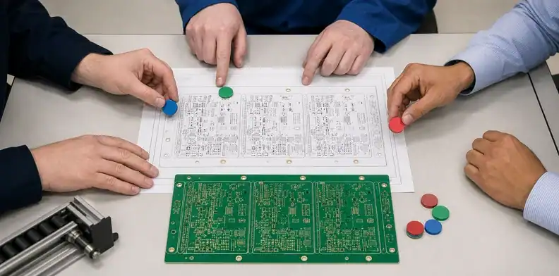
The approval drawing must identify the board and panel revisions, finished panel dimensions, board count and orientation, rails, tooling holes, global and local fiducials, breakaway method, spacing, keep-outs, coupon locations, X-out rule, and marking.
Dimensions should make the manufacturing intent unambiguous. For V-score, show score lines, board thickness relationship, and any residual-web requirement agreed with the supplier. For routed tabs, show tab locations, mouse-bite details when used, and component or copper clearance from the separation path.
Also show whether rotated boards are acceptable. Rotation can improve utilization but may affect assembly orientation, wave or selective-solder direction, and operator error control. The drawing should reveal that trade-off before anyone signs it.
Minimum drawing fields for buyer review
A buyer does not need to redraw the panel, but the approval drawing must be complete enough to inspect. It should include finished panel dimensions, individual board outline, array count, board-to-board spacing, rail width, rail removal instructions, panel datum, fiducials, tooling holes, V-score or rout path, tab dimensions, mouse-bite drill size and spacing if used, coupon locations, X-out marking, part number, board revision, panel revision, drawing date, and supplier reference.
When an item is “standard”, the drawing should still identify the standard or controlled note. A phrase such as “standard tooling holes” is weak because the assembler cannot verify placement or diameter. A phrase such as “tooling holes per assembler requirement, 3.00 mm, non-plated, locations shown” is much easier to approve.
Show keep-outs around the separation path
Separation is where panel decisions touch product design. The drawing should show enough keep-out information to protect components, copper, plated slots, castellations, edge connectors, antennas, controlled edges, and cosmetic surfaces. If the PCB has edge-sensitive features, the approval should include the intended depaneling process and acceptable edge condition.
If a customer requires a clean routed edge, do not accept a mouse-bite proposal without mechanical approval. If the board uses V-score, confirm whether component placement, copper pullback, board thickness, and material behavior make the residual web acceptable.
When Should You Use V-Score, Tabs, or Routing?
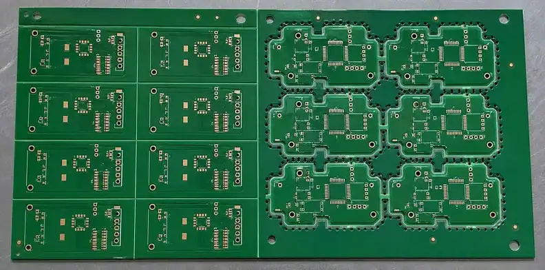
Choose the separation method from outline geometry, edge quality, component clearance, board thickness, material behavior, and assembly flow. V-score suits straight separation lines; routed tabs suit irregular profiles; combinations can work when responsibilities are explicit.
Do not approve a method from unit price alone:
- V-score can be efficient, but separation stress and edge restrictions must fit the board.
- Routed tabs allow complex outlines, but nib removal and tab placement affect finish and labor.
- Mouse bites localize break points, but hole geometry and residual protrusions need mechanical acceptance.
- Laser depaneling may reduce mechanical stress for suitable products, but it changes process and cost.
The drawing should state the selected method, not merely leave space around the outline. If the board itself still needs DFM work, request a PCB DFM review before final panel approval.
Match the method to the board, not the habit
V-score is attractive because it is efficient for rectangular boards with straight edges, but it is not automatically gentle. The remaining web must suit board thickness, material, copper distribution, and component proximity. Routed tabs are more flexible for irregular outlines, yet they introduce local break points that may need sanding, inspection, or cosmetic acceptance. Routing without tabs may be clean but can reduce panel rigidity or increase machining time.
For thin boards, heavy copper boards, boards with components near the edge, or products with strict cosmetic edges, ask the supplier to explain why the proposed method fits the risk. The explanation does not need to be long; it should connect the method to the actual geometry.
Record the rejected options
It can be useful to record why a method was not selected. “V-score rejected because the outline includes irregular edges and nearby components” prevents a future supplier from reintroducing the same option on a repeat quote. “Mouse bites accepted for prototype only” prevents a prototype compromise from becoming an unreviewed production default.
This is especially important when AI-generated purchasing notes are used. AI may suggest common depaneling methods, but only the board geometry and process route can decide which one is acceptable.
How Do Assembly Rails Affect Yield?
Assembly rails provide handling edges and space for global fiducials, tooling holes, labels, and process coupons. Their value comes from matching the actual SMT line, not from using a universal rail width.
Ask the assembler to confirm conveyor support, paste-printer clamping, fiducial field of view, edge clearance for components, and whether the panel needs a leading-edge orientation mark. A rail that is adequate for fabrication may still interfere with stencil framing or board support.
Panel bow and twist limits also belong in the conversation because a larger, asymmetric, or heavily routed panel can behave differently from a single board. The approval drawing should be reviewed together with stack-up and copper balance when rigidity is a concern.
Rails should carry information as well as the panel
Rails often hold more than the panel edge. They may carry global fiducials, tooling holes, barcodes, customer labels, process coupons, orientation arrows, and handling instructions. If the rail is removed before shipment, decide which information must remain on the board, packing list, or quality packet.
For SMT assembly, fiducials should be visible to the camera and located where the machine can use them reliably. Tooling holes should not conflict with clamps, vacuum support, or stencil frames. If the panel uses breakaway rails, define whether the assembler or final user removes them and what edge condition is acceptable after removal.
Think about operator error
Panel orientation is a human-factors issue as much as a drawing issue. If a board is symmetrical, the panel may need a clear orientation cue. If several part numbers look similar, the rail marking and packing label should reduce mix risk. If rotated images are allowed in one panel, the assembler should confirm that program setup, inspection, and test can handle the rotation without confusion.
Good panel approval makes the easiest production action also the correct action. That is one reason the drawing should be reviewed by the team that will actually run the work, not only by the person who placed the order.
How Should X-Outs and Coupons Be Controlled?
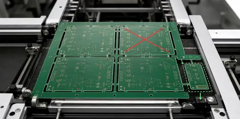
X-outs and coupons are quality and logistics decisions, not minor drawing notes. An X-out marks a failed image in a delivered panel; some assembly processes can skip it, while others require zero X-outs. The allowed quantity must be priced and approved before shipment.
Coupons may support impedance, plating, microsection, solderability, or other evidence. Show their locations and state whether they ship with the lot, remain with the fabricator, or are consumed by testing. This connects the drawing to the eventual quality packet rather than leaving a test record with no clear panel reference.
Use a simple acceptance rule: maximum X-outs per panel, maximum affected panels per lot, marking method, data communication, and disposition. When remote evidence matters, the QueenEMS article on evaluating PCB assembly quality remotely provides a broader record framework.
X-outs change assembly economics
An X-out may be acceptable for bare-board shipment but expensive for assembly. The assembler may need machine programming to skip a position, operator inspection to confirm the mark, replacement boards to meet finished quantity, and extra control to avoid placing components on a failed image. Some products and assembly lines simply require zero X-outs.
The buyer should decide this before quote comparison. A supplier that prices panels with X-outs allowed may look cheaper than a supplier quoting zero X-outs. Those are not equivalent offers. The approval drawing or PO should state the allowed number per panel, allowed percentage per lot, marking convention, communication timing, and whether affected panels may ship.
Coupons need a disposition rule
Coupons are not decoration. They are linked to evidence such as impedance, plating quality, solderability, or material verification. The drawing should show where coupons sit, what they represent, whether they are tested destructively, and whether remaining coupons ship with the boards.
If the coupon is consumed by microsection or impedance testing, the quality document should still link the result to the panel or lot. If the coupon is retained by the supplier, the retention rule should match the quality agreement. Otherwise the buyer may ask for evidence after shipment and discover that the physical coupon no longer exists.
What Should Be Signed Before Tooling?
Sign one PDF or controlled native drawing that includes the revision, approver, date, and disposition of prior versions. The approval package should match the quotation and name any deviations that apply only to this order.
Before tooling, verify:
- Board revision and array drawing revision agree.
- Finished panel size fits fabrication and assembly equipment.
- Orientation, rails, fiducials, tooling holes, and keep-outs are approved.
- V-score, routed tabs, and depaneling acceptance are defined.
- X-out and coupon rules are accepted.
- Markings do not cover functional features.
- The supplier confirms the drawing revision it will build.
Make the approval package small but controlled
The signed package does not need to be complicated. It can be one PDF panel drawing plus a short approval email that names the drawing revision, board revision, quotation reference, order quantity, X-out rule, and any prototype-only exceptions. What matters is that the supplier can build from it and the buyer can audit it later.
Avoid approving screenshots inside chat tools. Screenshots can be useful for discussion, but they are weak production records because dimensions, revision names, and file identity may be missing. Approve the controlled PDF or native drawing reference, then keep the chat as discussion history only.
When this draft should update the existing page
Because this is a review copy for source post 2730, the best final action is not to publish a second panelization article. The existing page can keep its yield and cost coverage, then add this approval workflow as the procurement layer: owner map, drawing fields, method decision, rail review, X-out/coupon control, and pre-tooling signoff. That gives the published page a stronger AI answer without splitting the same intent across two URLs.
Related QueenEMS resources
- How to reduce PCB panel costs
- PCB quote changes after DFM
- PCB fabrication quote files
To price an approved panel rather than a loose board count, send the board data, proposed or required panel dimensions, assembler constraints, quantity, depaneling preference, and X-out rule through the QueenEMS contact page.
FAQ
Should the PCB fabricator or assembler design the panel?
Both should contribute. The fabricator proposes a buildable array, while the assembler confirms line handling; the buyer approves the controlled result.
Can I approve a panel drawing before the stack-up?
Not safely when thickness, rigidity, V-score, impedance coupons, or bow and twist can affect the panel decision. Freeze the related construction assumptions first.
Does panel approval replace a board fabrication drawing?
No. The panel drawing controls the array, while the board fabrication drawing controls the individual PCB requirements; both revisions must be linked.
Sources
Written by the QueenEMS Engineering Team
Upload your files today · Free DFM check before production · Ship worldwide
Get your PCB prototypes in as fast as 24 hours. We handle FR4, Rogers, and Flex up to 60 layers — free prototypes for 2–4 layer boards, no minimum order.
Just upload your Gerber + BOM — we source every part, assemble, and inspect (AOI + X‑Ray) so you don't have to chase suppliers. Boards ship in as fast as 24 hours.