
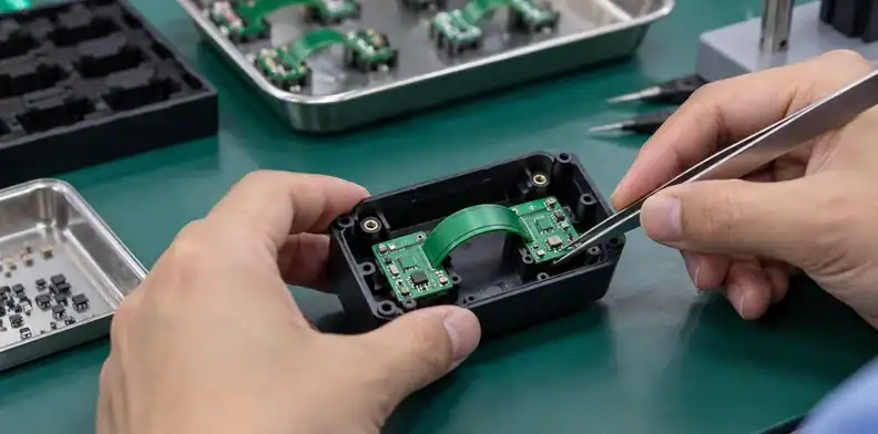
Quick Answer: A semi flex PCB can use a locally thinned FR4 region to connect rigid sections that are bent into a fixed installation position. Its suitability depends on the remaining laminate and copper, the formed geometry and the way the assembly is supported. Treat the bend as a construction-specific installation operation; neither a universal radius nor a generic bend-cycle allowance qualifies the design.
A semi flex PCB becomes worth assessing when a product needs two rigid circuit sections at different angles but the interconnect remains stationary after installation. Removing buildup in a defined region can allow that connection to curve into the housing. The proposal must address what survives the thinning process and how the completed circuit reaches its installed shape without damage.
Table of Contents
- What makes a semi flex PCB different?
- Which products fit a fixed installation bend?
- Read the thinned section as a complete cross-section
- Why thickness and radius must be assessed together
- Lay out the bend and its transition regions
- Make milling variation visible before the first fold
- Plan assembly while the circuit is still flat
- Form the bend once the assembly is ready
- Validate the installed shape, not only the bare board
- Compare the proposal against cables and rigid-flex
What makes a semi flex PCB different?
For the semi flex PCB construction discussed here, a thin remaining FR4 connection bends between rigid board sections. This is a specific approach to fixed installation, and the term should be clarified because suppliers can use semi-flex or semi-rigid for different constructions.
The remaining FR4 carries the installation bend
FR4 is a glass-reinforced resin laminate. For example, Isola describes FR408HR as reinforced with E-glass fabric. Thinning such a structure does not turn its reinforcement into a polymer film. That material description supports the distinction; the FR408HR page does not qualify it for the semi-flex geometry in a particular product.
The useful drawing therefore shows the remaining structure in the bend, not only the full rigid-board thickness. Material grade, surviving copper and the local removal boundary all need explicit identification. General FR4 material selection remains relevant, but a thermal grade designation alone cannot establish bending suitability.
A rigid-flex hinge uses a different material system
Conventional rigid-flex commonly combines rigid regions with a purpose-designed flexible dielectric structure, often polyimide. Its material and processing choices differ from a locally thinned FR4 connection. A familiar rigid-flex drawing should not be reused without checking what actually bends.
The Pyralux TK and AP comparison concerns flexible material selection. Use that route when flexible laminate is under consideration. For the FR4 approach, first confirm that the fabricator’s proposal truly retains a thinned glass-reinforced region rather than substituting an entirely different hinge.
Which products fit a fixed installation bend?
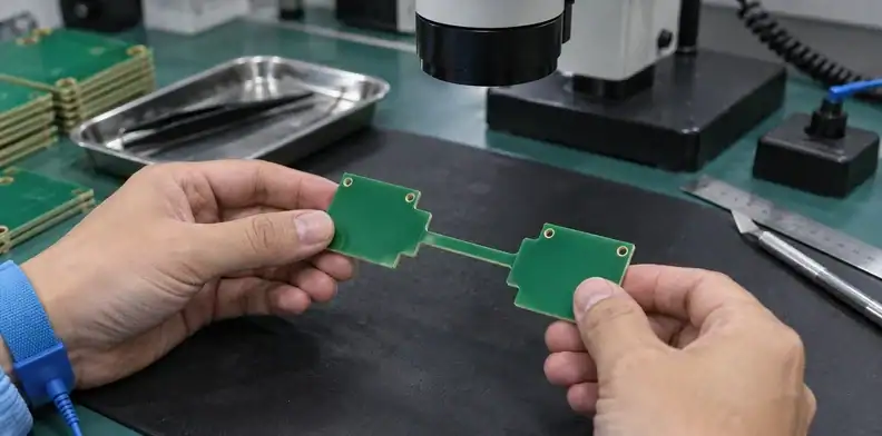
Start with the product’s physical movement. A circuit that curves during installation and then remains restrained is a candidate for assessment; a moving hinge needs a different construction and qualification discussion.
| Product condition | Why it changes the decision | Initial approach |
|---|---|---|
| Two board sections mounted on different fixed housing planes | The connection needs an installation curve | Assess the named semi-flex construction and forming access |
| Circuit fitted around a stationary internal obstruction | Available length and clearance determine the curve | Check the complete installation path, not just its final angle |
| Housing opened for maintenance | Service may reverse or repeat the bend | Define service motion before accepting a static proposal |
| Moving display, articulated joint or operating hinge | Motion continues during product use | Investigate a qualified dynamic interconnect |
| Product movement has not yet been defined | The required mechanical duty is unknown | Resolve the product requirement before choosing construction |
Consider an instrument with a front display board and a side-mounted sensor board. A fixed internal connection may remove a separate cable assembly, but the housing must offer room to form and secure it. This is an illustrative application, not evidence that a specific FR4 stack has passed qualification.
A second example is a sealed module that must be opened for occasional repair. Calling its bend “static” would miss the service operation if technicians have to unfold the circuit. Count assembly, test, rejected installation attempts and service movements as separate events in the proposed process. The fabricator must assess that actual sequence rather than an assumed one-time fold.
Read the thinned section as a complete cross-section
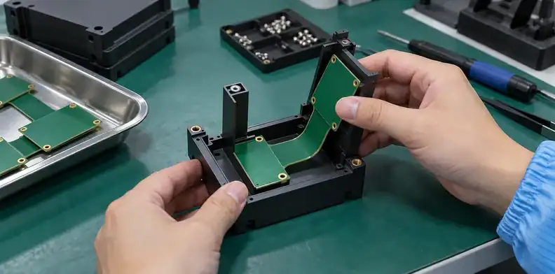
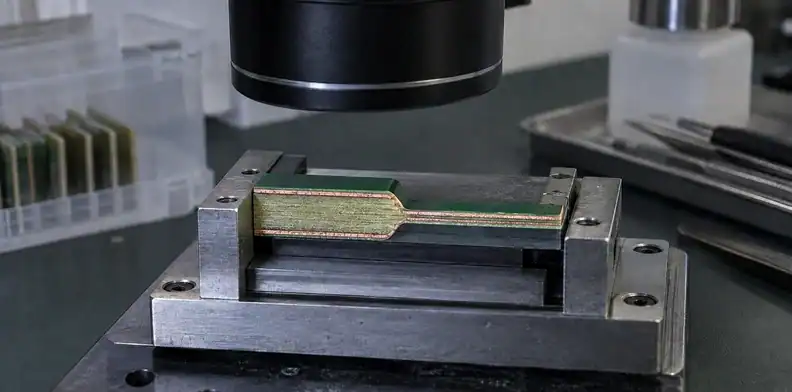
Review every material that remains in the curved region and every layer that stops before it. The residual cross-section controls the bending behavior, while the rigid sections still need to carry components and mounting loads.
| Cross-section object | What the drawing must identify | Why it matters |
|---|---|---|
| Remaining dielectric | Material identity and finished local thickness | Establishes the material subjected to bending |
| Surviving copper | Layer position, thickness and connected nets | Defines the conductors that must remain intact |
| Removed buildup | Which layers are removed and from which side | Prevents contradictory assumptions about copper continuity |
| Protective coating | Material and coverage on the remaining region | Adds to the local structure and must tolerate the operation |
| Transition shoulder | Boundary between rigid and thinned regions | Locates the change in stiffness and support |
| Finished rigid regions | Thickness, component locations and mounting features | Establishes the loads that must bypass the thin link |
A full-board layer count is insufficient. Two proposals with the same number of rigid-region layers can leave different copper and dielectric arrangements in the connecting strip. Review a section through the bend and another through the transition so the fabricator and mechanical designer are evaluating the same object.
The stepped-thickness stackup discussion covers thickness regions and layer continuity. Here, the additional question is whether the remaining region can reach and retain the required installed curve. A thin region made for clearance may still be unsuitable for bending.
Do not approve a drawing that names only a milling depth. Obtain the resulting residual structure as well. It lets the reviewer see whether the proposed operation leaves the dielectric and copper that the bend assessment assumes.
Why thickness and radius must be assessed together
A thinner region and a larger curve can reduce geometric bending strain, but neither change proves that a particular laminate-and-copper construction is acceptable. Use the relationship to understand the proposal, then qualify the actual structure.
A geometric illustration of bending strain
David Roylance’s MIT beam-bending notes explain how longitudinal strain changes with distance from the neutral axis and curvature. The neutral axis is the position through the thickness where longitudinal bending strain is zero in the simplified model.
For an illustrative, homogeneous strip with its neutral axis at mid-thickness and a uniform circular bend, outer-surface strain magnitude is approximately thickness divided by twice the neutral-axis radius. A hypothetical 0.20 mm strip around a 10 mm neutral-axis radius gives 0.20/(2 × 10), or 1%. At the same radius, a hypothetical 0.30 mm strip gives 1.5%. These numbers illustrate geometry only; they are not recommended semi-flex thicknesses or allowable FR4 strains.
Why the illustration is not a design limit
A real PCB is a layered composite. Copper distribution, reinforcement, coatings and an asymmetric residual section can shift the neutral axis. Milling shoulders and a locally forced crease also depart from a smooth uniform curve. The simple calculation cannot establish copper fatigue, laminate fracture or acceptable installation life.
Use this analysis to question a proposal that changes residual thickness while keeping the same claimed forming conditions. The appropriate next evidence is an assessment and sample validation tied to the proposed materials and geometry. Also specify whether a drawing radius refers to the inside surface, neutral axis or forming tool; those references should not be silently interchanged.
Lay out the bend and its transition regions
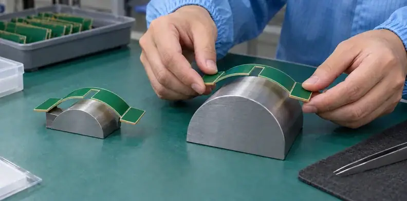
Reserve the curved region for the intended connecting structure, and keep assembly loads on the rigid sections. The layout review should examine where the curve begins, where it ends and how conductors cross both transitions.
Mark a bend zone with a length and boundary, rather than a line that invites an installer to create a sharp crease. Show the direction and final orientation of the rigid sections. Add the housing envelope so the bend cannot be approved in isolation from the product it must enter.
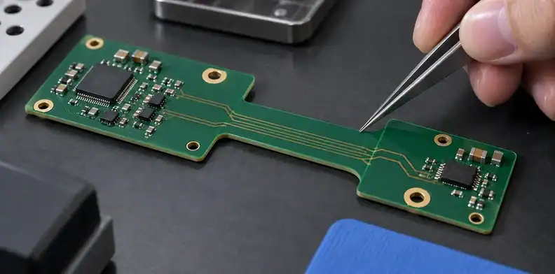
Within the candidate bend, review trace direction, width changes and copper distribution with the fabricator. Abrupt conductor changes deserve attention because they alter the local geometry being strained. Broad planes and asymmetric copper also change the section being assessed. Any electrical route that cannot be modified should be identified before a mechanical improvement is proposed.
Components, mounting holes and connector retention should be located where the rigid structure can support their loads. Ask the fabricator to identify the required exclusion regions for its particular transition process. Avoid converting a different supplier’s published keepout distance into a universal rule.
This review also needs installation access. A finger, tool or fixture must be able to form the strip without pressing on small components or dragging the board across a sharp housing edge. Once the circuit is mounted, a connector insertion force should enter a rigid support rather than twist the thin link. Place those supports in the mechanical model before freezing the bend region.
Make milling variation visible before the first fold
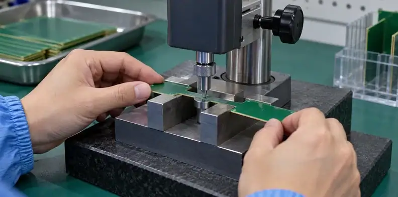
Inspect the residual structure that will bend, because successful machining to a nominal depth does not by itself establish a consistent remaining section. Agree how local thickness and transition condition will be verified before forming the assembly.
| Feature to verify | Useful evidence | Question it closes |
|---|---|---|
| Residual thickness across the linking region | Defined measurement locations and method | Does the actual strip match the assessed section? |
| Preserved copper layer | Appropriate cross-section or process verification | Was the intended conductor retained? |
| Transition position | Dimensional inspection against the bend drawing | Does the smooth curve fit between the rigid regions? |
| Milled surface and shoulder | Magnified inspection using agreed acceptance criteria | Is there machining damage requiring disposition? |
| Lot relationship | Traceable sample or coupon record | Does the supporting evidence represent this production lot? |
The detailed datum and tolerance questions belong with controlled-depth routing requirements. For semi-flex installation, connect their result to the bend assessment: a measurement report needs to describe the material left behind, not only the material removed.
Select an inspection method that does not crush or deflect the strip while measuring it. Discuss fixture support and contact force when a thin region makes measurement sensitive to handling. A coupon can help investigate the cross-section, but it must represent the relevant stack and machining operation.
The PCB microsection report discussion helps interpret section evidence. Destructive inspection confirms the sampled structure; it does not mean every shipped board was sectioned. Define how that sample supports the lot before relying on it for release.
Plan assembly while the circuit is still flat
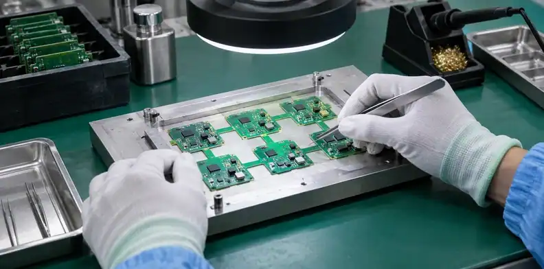
Develop the assembly sequence around support of the thin connection, then identify the operation that changes the circuit from flat to formed. Leaving the bend stage unspecified can expose the strip to uncontrolled handling throughout assembly.
Review the panel, carrier and component access together. The thin region may need support during printing, placement, soldering, inspection or separation from the panel. The carrier must also release the assembly without forcing a premature bend. A plan that works at the placement machine can still fail when an operator removes the board.
A practical sequence for evaluation is to complete the compatible flat-assembly operations, inspect the connection and accessible joints, and then form the circuit in the approved fixture. That is a proposed workflow, not a universal process prescription. The actual materials, equipment and product determine whether another sequence is needed.
Put the fold stage and support points into the PCBA assembly drawing so the installed shape is not communicated only through a mechanical designer’s email. Include which surfaces may contact the fixture and where populated components need clearance.
Testing also affects handling. If the fixture requires a flat circuit after installation, it may force an additional unfolding operation. Resolve that conflict while test points and carriers can still be changed. The process should reveal every intentional movement of the thinned region before the construction is approved.
Form the bend once the assembly is ready
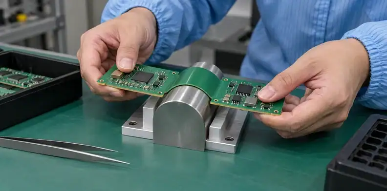
Guide the connection into a controlled curve while supporting both rigid sections, then restrain the installed circuit so the thin region is not used as a structural hinge. The fixture and housing should implement the assessed geometry.
Guide the curve without making a crease
Use the agreed forming surface and direction rather than pinching the strip at a single point. Observe the transition regions while the rigid sections move toward their installed positions. Stop when an unexpected obstruction, visible damage or abnormal resistance to forming appears; forcing the angle can hide an incompatible geometry.
Do not apply heating or other forming treatments by improvisation. Any such step needs a process tied to the actual laminate, coating and populated assembly. Likewise, a curved sample from another supplier does not establish that this structure can tolerate the same operation.
If assembly access forces the board through a tighter temporary curve than its final installed shape, that temporary condition must be assessed too. The finished photograph alone would omit the most demanding part of installation. A forming trial should therefore reproduce the complete motion path through the housing.
Let the housing carry loads after installation
Support and secure the rigid regions in their final positions without stretching or twisting the connecting strip. Check that fastening one board does not pull the other into alignment through the bend. Mounting variation can turn a nominally static connection into a loaded spring.
Provide room for the formed connection around covers, internal ribs and cables. In the fixed display-and-sensor example, the mounts carry connector forces and the curved strip provides the electrical link. If opening the cover moves that strip, record the service condition and reopen the construction assessment rather than treating it as ordinary static use.
Validate the installed shape, not only the bare board
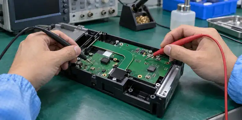
Validation must represent the circuit’s full assembly and installation path. A flat bare-board electrical test cannot show whether forming, mounting or service access damages the completed connection.
| Validation stage | What to examine | Evidence to preserve |
|---|---|---|
| Before forming | Residual structure, surface condition and electrical baseline | Identified sample, measurements and inspection views |
| During installation trial | Tool access, temporary curvature and transition movement | Fixture setup and sequence record |
| After mounting | Visible condition, actual curve, twist and housing clearance | Installed photographs and fit results |
| Electrical verification | Nets or functions affected by the curved region | Defined endpoints, conditions and acceptance results |
| Relevant product exposure | Response to the specified environment or service movement | Test plan and results tied to the installed configuration |
Set acceptance criteria before the trial. Include which observations require a hold, who dispositions them and whether a failed sample triggers a change to the strip, housing or forming fixture. Avoid an undefined test instruction such as “bend carefully and confirm it works.”
An illustrative pilot build might pass electrical checks while flat but develop intermittent behavior after mounting. Investigation should preserve its installed shape and compare the measured residual section, transition condition and housing fit with the assessed proposal. Repeatedly flattening it for diagnosis can change the evidence and add movements that were never approved.
Select further testing according to the product environment. The PCBA reliability-testing discussion helps define test purpose, but a general burn-in requirement does not replace installation-specific checks. Keep the forming setup and accepted construction with the test record so the result can support a repeat build.
Compare the proposal against cables and rigid-flex
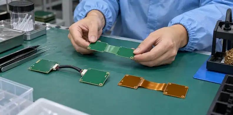
Compare complete installed constructions after their mechanical duties are understood. Locally thinned FR4 can remove separate interconnect parts in some fixed layouts, but machining, support and validation remain part of its cost and feasibility.
| Construction | Reason to assess it | Project question that decides suitability |
|---|---|---|
| Locally thinned FR4 semi-flex | Continuous connection between fixed rigid regions | Can the named residual structure survive the complete installation and specified service path? |
| Separate rigid boards with cable or connector | Independent board mounting and service separation | Is space, retention and connector access available? |
| Purpose-designed rigid-flex | Flexible material structure integrated with rigid sections | Does the qualified flex stack fit the required movement and electrical duty? |
Use the rigid-flex and flexible-circuit cost factors for that separate material-and-cost decision. Do not apply a fixed saving percentage to semi-flex. Compare quotations that include the same assembly operations, fixtures, inspection and product validation assumptions.
A useful semi-flex proposal identifies the remaining cross-section, curve reference, forming method, rigid-section supports and any restriction on service movement. If the fabricator changes copper, residual thickness or removal boundaries, engineering needs to reassess the installed construction. A price for a modified structure should show those changes explicitly.
For a project assessment, send QueenEMS the board and housing files, the proposed residual section and a description of every installation and service movement, so the construction’s feasibility and missing validation inputs can be reviewed before a manufacturing commitment.
FAQ
Does semi-flex always mean locally milled FR4?
Terminology varies. This article addresses that construction specifically; ask the fabricator to show the remaining material structure before comparing it with another semi-flex proposal.
Can a standard rigid FR4 board be bent after delivery?
Do not infer suitability from the material name. The connecting region must be designed, fabricated and assessed for the proposed operation. Bending an ordinary rigid section is not an equivalent manufacturing approach.
Can supplier bend limits be reused for a second source?
Only after the second source’s construction and evidence have been evaluated. A published limit can belong to a particular material, copper, process and geometry rather than the entire semi-flex category.
Should the board ship flat or already formed?
Agree this with the assembly and packaging plan. Either choice must preserve the assessed geometry and account for handling, test access and all further movements during installation.
Sources
- Isola: FR408HR glass-reinforced laminate description, used for material context rather than semi-flex qualification.
- MIT OpenCourseWare: David Roylance, Stresses in Beams, used for the bounded geometric illustration.
Written by the QueenEMS Engineering Team
Upload your files today · Free DFM check before production · Ship worldwide
Get your PCB prototypes in as fast as 24 hours. We handle FR4, Rogers, and hybrid boards up to 40 layers in volume production, with advanced builds subject to engineering review — free prototypes for 2–4 layer FR-4 boards, no minimum order.
Just upload your Gerber + BOM — we source every part, assemble, and inspect (AOI + X‑Ray) so you don't have to chase suppliers. Boards ship in as fast as 24 hours.