
You can save up to 30% on bare board manufacturing costs by matching your printed circuit board’s thermal profile to the exact Tg grade required instead of defaulting to premium laminates. Many engineering teams over-specify their substrate out of fear, paying premium prices for heat resistance that a standard consumer device never utilizes. We will explain exactly how to specify your FR4 material to stop wasting your hardware budget while maintaining absolute field reliability.
Quick Answer: You should specify standard Tg130 for 2-4 layer boards operating below 100°C, saving 20-30% on fabrication costs. Upgrade to Tg150 or Tg170 only when your specific design requires multiple lead-free reflow cycles or operates continuously above 130°C. Key takeaways:
- Standard 130°C grades handle single-pass lead-free reflow perfectly well.
- Z-axis expansion jumps 4-8× above the Tg point, causing immediate via cracking.
- Premium high-heat materials cost $0.30-$0.50 more per standard 4-layer unit.
- Decomposition temperature (Td) protects your bare board better than Tg during soldering.
Table of Contents
- What Is Standard FR4 Laminate and Why Does Tg Matter?
- How Are High-Tg PCB Grades Classified Under IPC-4101?
- What Happens to Your Circuit Board When Temperature Exceeds Tg?
- When Does Standard Tg130 FR4 Work Fine for Your PCB?
- Why Should You Choose Tg150 as the Mid-Range Option?
- How Does Lead-Free Soldering Change Your FR4 Tg Requirements?
- What Is the Real Cost Difference Between Tg130, Tg150, and Tg170?
- Does Higher Tg Always Mean Better Signal Integrity?
- Which FR4 Brands Should You Specify for Fabrication?
- How Do You Select the Right FR4 Material for Your Next Project?
What Is Standard FR4 Laminate and Why Does Tg Matter?
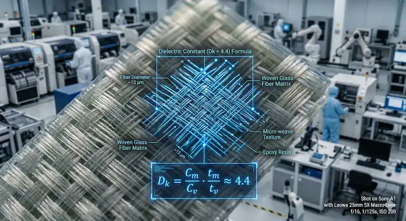
Standard FR4 laminate is a flame-retardant glass-reinforced epoxy, and its Tg determines the exact temperature where the material softens. Tg matters because crossing this 130°C threshold causes the resin to expand rapidly, which means your copper vias will fracture under severe mechanical stress.
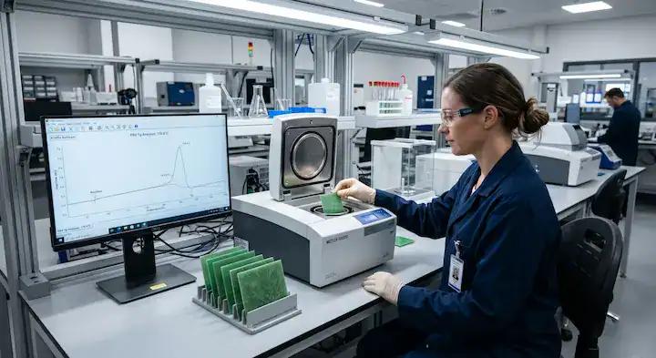
The IPC-TM-650 Test Methods Manual specifies Differential Scanning Calorimetry (DSC) for measuring this thermal shift accurately. Commercial laminates must also pass the UL 94V-0 flammability rating to prove they self-extinguish within 10 seconds.
How Does Heat Affect Resin Structure?
Glass Transition Temperature (Tg) is the exact thermal point where rigid epoxy shifts into a soft, rubbery state. Standard FR4 Tg sits strictly between 130°C and 140°C across the manufacturing industry.
Here is the truth:
- The rigid state maintains via structural integrity perfectly.
- The rubbery state allows massive and unpredictable Z-axis swelling.
What Are the Operating Boundaries?
Your circuit board should never operate continuously near its structural transition point. The standard thermal safety margin requires keeping ambient internal temperatures 20°C to 25°C below the rated specification.
Key Takeaway: Proper specification prevents mechanical stress from tearing your copper plating apart. Bottom line: Always maintain a 25°C buffer between your device’s maximum operating temperature and the laminate’s rated threshold.
| Property | Standard FR4 Data | High-Tg Data |
|---|---|---|
| Tg Range | 130-140°C | 170°C+ |
| UL Rating | 94V-0 | 94V-0 |
| Best For | Basic electronics | High-heat devices |
This data proves that standard laminates cover most basic thermal requirements without forcing you into premium price tiers.
How Are High-Tg PCB Grades Classified Under IPC-4101?
High-Tg PCB grades are officially categorized by the IPC-4101 specification using numbered slash sheets. Slash sheet /21 dictates properties for standard 130°C laminates, while /26 mandates the strict thermal requirements for 170°C and above.
These universal standards establish a clear technical language between design engineers and fabrication facilities. They remove ambiguity by requiring specific testing minimums for every raw resin batch entering the factory.
What Do Slash Sheets Actually Specify?
The specification sets exact minimums for thermal degradation and delamination times. Decomposition Temperature (Td) is the thermal point where resin permanently loses 5% of its physical mass. Standard Td sits predictably around 305°C.
Consider this fact:
- Slash /21 requires standard testing baselines for normal environments.
- Slash /26 demands extended physical survival at extreme 288°C heat.
Why Are Testing Methods So Strict?
Manufacturers use the T288 test to measure how many minutes the material survives at 288°C before physically separating. Standard grades last approximately 5 minutes, while high-performance variants survive up to 30 minutes under the same heat.
Key Takeaway: Relying on official IPC classifications prevents dangerous miscommunication with your factory floor. Bottom line: Always call out the exact IPC slash sheet on your fabrication drawing to guarantee structural material compliance.
| IPC Slash Sheet | Minimum Tg | Typical Td |
|---|---|---|
| IPC-4101/21 | 130°C | 305°C |
| IPC-4101/26 | 170°C | 340°C+ |
The strict jump in Td requirements for the /26 sheet demonstrates its readiness for extreme surface mount assembly conditions.
What Happens to Your Circuit Board When Temperature Exceeds Tg?
When your circuit board crosses the transition threshold, the standard FR4 Z-axis coefficient of thermal expansion (CTE) violently jumps by 4 to 8 times. Copper only expands at 17 ppm/°C, while the heated resin hits 300 ppm/°C, resulting in immediate via cracking and pad lifting.
This severe mechanical mismatch rips apart the delicate copper barrels lining your through-holes. Any design utilizing multilayer PCB fabrication multiplies this specific risk due to the accumulated resin thickness pushing against the vias.
How Does Z-Axis Expansion Destroy Vias?
Below the transition point, the resin expands at a manageable 50-70 ppm/°C. Once heated past the threshold, the chemical matrix softens and swells uncontrollably strictly along the vertical axis.
Pay attention to this mechanism:
- The softened epoxy pulls upward forcefully against the copper walls.
- The rigid copper barrel fractures entirely under the tensile load.
Can Layer Count Accelerate Failures?
A client experienced persistent via cracking on their 10-layer control boards running continuously at 145°C on standard Tg135. We upgraded their stackup to a 170°C grade, which means the CTE remained perfectly stable at their operating temperature, resulting in a 0% failure rate across 5,000 active units.
Key Takeaway: Matching thermal limits directly prevents catastrophic mechanical separation inside your plated holes. Bottom line: Never allow operating temperatures to cross the transition threshold on boards thicker than four layers.
| Material State | Z-axis Expansion Rate | Copper Expansion Rate |
|---|---|---|
| Below Tg (Glassy) | 50-70 ppm/°C | 17 ppm/°C |
| Above Tg (Rubbery) | 250-300 ppm/°C | 17 ppm/°C |
The massive expansion multiplier above the transition phase clearly highlights the primary physical mechanism for internal barrel cracking.
When Does Standard Tg130 FR4 Work Fine for Your PCB?
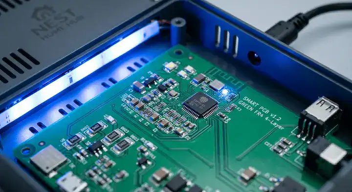
Standard Tg130 FR4 works flawlessly for 2-4 layer consumer products that run below 100°C and require only a single reflow cycle. You save 20-30% on bare board expenses immediately because the design never stresses the resin’s thermal limits.
PCB design forums frequently ask: “My board is a simple 4-layer consumer product that runs cool — do I really need to pay extra for high-Tg material?” The absolute answer is no, provided you meet basic assembly criteria.
What Are the Safe Operating Conditions?
If you utilize tin-lead solder, reflow peaks only hit 215-230°C, staying well within safe processing boundaries. Even for simple lead-free profiles, a single heating pass rarely degrades standard resin structures enough to cause harm.
Keep these rules in mind:
- Limit assembly processing to a single thermal pass.
- Keep ambient product environments steadily below 85°C.
How Does Standard Resin Benefit Prototyping?
Utilizing baseline laminates accelerates manufacturing timelines and reduces upfront capital waste. When you utilize rapid PCB prototyping services, specifying basic grades keeps your iterative testing budget incredibly lean.
Key Takeaway: Over-engineering your substrate wastes budget with zero measurable physical field benefits. Bottom line: Specify 130°C laminates for all simple consumer devices operating in cool, indoor environments.
| Application Parameter | Standard 130°C Suitability |
|---|---|
| Layer Count | 2 to 4 layers |
| Solder Type | Tin-Lead or Single Lead-Free |
| Ambient Temp | Below 85°C |
These parameters confirm that the majority of everyday electronics function flawlessly on the most economical substrate available.
Why Should You Choose Tg150 as the Mid-Range Option?
You should choose Tg150 FR4 laminate when your board requires double-sided lead-free assembly but operates in normal temperature environments. This mid-tier selection prevents reflow delamination while keeping material costs 10-15% lower than premium 170°C options.
Many designers default to the highest specification available when faced with complex assembly steps. The 150°C rating acts as the perfect structural compromise for modern surface mount technologies.
When Is the Mid-Tier Grade Perfect?
Devices like industrial controllers or automotive cabin electronics often push past 100°C ambient temperatures. A 150°C rating provides the mandatory 25°C safety buffer without triggering massive procurement cost penalties.
Look at these clear advantages:
- Survives multiple soldering passes reliably without blistering.
- Avoids the steep price jumps associated with aerospace grades.
How Does It Compare to Advanced Substrates?
Sometimes thermal loads exceed basic epoxy capabilities entirely due to massive power components. For extreme heat dissipation, reviewing a ceramic PCB vs FR4 comparison makes more sense than merely increasing the epoxy threshold.
Key Takeaway: The 150°C grade delivers the precise thermal durability required for standard dual-sided manufacturing processes. Bottom line: Default to the 150°C option for double-sided lead-free boards operating below 120°C.
| Specification | Tg130 | Tg150 | Tg170 |
|---|---|---|---|
| Ideal Assembly | Single pass | Double pass | Complex/Heavy |
| Cost Premium | Base | +10% to 15% | +20% to 40% |
The mid-range option precisely balances manufacturing durability with reasonable budget constraints for modern automated assembly lines.
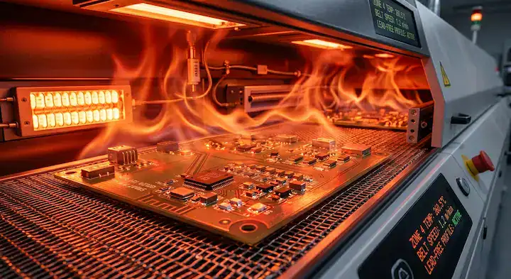
How Does Lead-Free Soldering Change Your FR4 Tg Requirements?
Lead-free soldering requires peak reflow temperatures of 245-260°C, which completely exceeds the Tg of all standard high-Tg FR4 variants. Because heat surpasses the transition point entirely, you must focus on a Decomposition Temperature (Td) of at least 340°C to prevent resin destruction.
Electronics manufacturing forums constantly ask: “We switched to lead-free and now our boards are delaminating during reflow — is this a Tg issue or a Td issue?” The real culprit is almost always a low decomposition threshold failing under heat.
Why Does Decomposition Temperature Matter?
Decomposition Temperature (Td) is the exact heat level where epoxy permanently loses physical mass. Standard grades with a Td of 305°C lose 1.5% to 3% of their mass at lead-free peaks, resulting in microscopic voids and explosive blisters.
Here is the exact mechanism:
- Trapped moisture and resin expand violently near 260°C.
- Low Td materials break down chemically, causing rapid delamination.
How Do Multiple Reflow Cycles Compound Stress?
A drone startup brought us 6-layer flight controllers experiencing 12% delamination using SAC305 solder at 250°C on standard Tg135. We switched them to Shengyi S1000-2 featuring a Td of 340°C, which means the resin survived dual reflows, resulting in zero failures and eliminating $4,800 in monthly rework.
Key Takeaway: Upgrading your substrate solely for Td performance eliminates blister defects during harsh, modern soldering profiles. Bottom line: Always specify a Td of 340°C or higher when subjecting boards to more than one lead-free thermal cycle.
| Solder Profile | Peak Temperature | Required Td Minimum |
|---|---|---|
| Tin-Lead | 215-230°C | 305°C |
| Lead-Free (Single) | 245-250°C | 320°C |
| Lead-Free (Double) | 250-260°C | 340°C+ |
The sharp rise in required Td minimums proves that modern soldering profiles destroy basic resins chemically, not just mechanically.
What Is the Real Cost Difference Between Tg130, Tg150, and Tg170?
Upgrading to premium FR4 laminate increases your bare board material expenses by 20% to 40% globally. For a typical 100x100mm 4-layer board, specifying 170°C resin adds $0.30 to $0.50 per unit over the standard 130°C baseline.
These fractional increases accumulate massively across large production volumes. Understanding this pricing scale empowers you to negotiate accurate rates with your fabrication partners based on realistic material pricing.
How Does Material Pricing Scale?
An industrial sensor company asked us to quote a 4-layer gateway board in both 130°C and 170°C formats. The standard grade cost $1.20 per board, while the premium grade quoted at $1.65, representing a massive 37.5% price premium.
Review these strict cost factors:
- Specialized resins require significantly more expensive raw chemicals.
- Longer factory pressing cycles consume much more machine electricity.
When Is the Premium Justified?
Because the gateway board operated at 45°C with a single tin-lead pass, we strictly recommended the 130°C grade. The client saved $4,500 over 10,000 units, which means they protected their profit margins without sacrificing a single device to thermal failure.
Key Takeaway: Arbitrarily demanding premium specifications directly damages your product’s market competitiveness and baseline profit margins. Bottom line: Never pay the 30% premium for high-heat materials unless your assembly or operating environment mathematically demands it.
| Material Grade | Example Price (100x100mm) | Cost Premium |
|---|---|---|
| Standard 130°C | $1.20 | Baseline |
| Mid-Tier 150°C | $1.38 | +15% |
| Premium 170°C | $1.65 | +37.5% |
These real-world pricing structures demonstrate exactly why correctly matching the substrate to the thermal load protects your production budget.
Does Higher Tg Always Mean Better Signal Integrity?
Higher Tg FR4 actually degrades signal integrity at frequencies above 5GHz because the modified resin structures increase signal absorption. High-heat materials feature a Dissipation Factor (Df) of 0.020-0.025, which means they perform noticeably worse than standard grades featuring a 0.015 Df.
RF design discussions frequently feature engineers asking: “I’m designing a 10GHz RF board — should I use high-Tg FR4 for better performance?” The scientific answer directly contradicts what most hardware developers assume.
Why Do High-Heat Resins Ruin High-Speed Signals?
Dissipation Factor (Df) is the strict measurement of how much electromagnetic energy the substrate absorbs and loses as heat. The chemical additives required to raise the thermal threshold inherently make the epoxy significantly more lossy at microwave frequencies.
Note these electrical truths:
- 130°C grades transmit 5GHz signals efficiently and cleanly.
- 170°C grades severely attenuate signals operating past 3GHz.
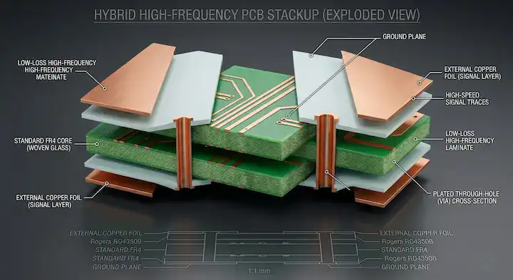
What Is the Hybrid Solution?
When your product demands both thermal resilience and extreme frequency performance, you must consult a PCB stack-up design guide. You build a hybrid stackup by placing high-frequency laminates on outer signal layers while utilizing rigid 170°C cores strictly for internal power planes.
Key Takeaway: Thermal stability and electrical purity are opposing chemical forces in standard epoxy engineering. Bottom line: Switch to specialized RF materials like Panasonic Megtron instead of premium FR4 when designing above the 5GHz frequency threshold.
| Material Category | Typical Tg | Dissipation Factor (Df) @ 1GHz |
|---|---|---|
| Standard Epoxy | 130°C | 0.015 – 0.018 |
| High-Heat Epoxy | 170°C | 0.020 – 0.025 |
| RF Specific (Megtron) | 185°C+ | 0.002 – 0.004 |
The electrical penalty embedded in high-heat epoxies becomes immediately obvious when comparing their elevated dissipation factors side-by-side.
Which FR4 Brands Should You Specify for Fabrication?
You should explicitly specify Shengyi S1141 for reliable standard high-Tg FR4 requirements and Shengyi S1000-2 when you need a verified 170°C rating. Naming exact brands prevents rogue factories from silently substituting low-quality epoxies that barely meet the IPC slash sheet minimums.
Allowing a fabricator to choose “any equivalent material” invites catastrophic risk directly into your supply chain. We audit incoming raw panels relentlessly to verify the exact brand markings pressed into the copper margins.
Which Materials Dominate the Industry?
The Asian manufacturing ecosystem heavily relies on Shengyi and Kingboard for consistent, voluminous supply chains. For specialized mid-loss applications requiring tight impedance control, Isola 370HR remains an absolute industry favorite across North American design hubs.
Trust these established product lines:
- Shengyi S1141 delivers bulletproof 130°C daily performance.
- Isola 370HR excels in multi-pass lead-free automated assembly.
Why Are Exact Specifications Mandatory?
Our engineering review caught a client submitting files calling generically for “High-Tg material.” We updated their drawing to explicitly demand Shengyi S1000-2, which means we blocked cheaper alternatives, resulting in a perfect 99.7% first-pass yield during assembly.
Key Takeaway: Controlling the exact bill of materials for your bare board is just as vital as controlling your silicon component choices. Bottom line: Always print the exact manufacturer and part number of your chosen laminate directly onto your fabrication drill drawing.
| Manufacturer | Material Grade | Target Application |
|---|---|---|
| Shengyi S1141 | 130°C (Standard) | Consumer / Cool devices |
| Isola 370HR | 150°C (Mid-Tier) | High-reliability IT |
| Shengyi S1000-2 | 170°C (Premium) | Industrial / Automotive |
Identifying trusted brand names gives your procurement team a reliable, auditable benchmark to measure factory quotes against.
How Do You Select the Right FR4 Material for Your Next Project?
You select the perfect FR4 material by documenting your lead-free reflow cycle count and establishing your product’s maximum continuous ambient temperature. By subtracting 25°C from the laminate’s rated threshold, you immediately identify if a 130°C, 150°C, or 170°C grade is legally required.
Engineering a successful hardware launch requires balancing thermal physics directly against rigid budgetary constraints. Let raw data drive your substrate decisions instead of relying on outdated tribal knowledge or fear-based engineering practices.
What Is the Final Decision Matrix?
Evaluate your layer count thoroughly before proceeding. Anything over six layers stores massive amounts of heat during reflow, pushing the baseline requirement instantly to 150°C to successfully combat Z-axis via fatigue.
Follow this strict evaluation sequence:
- Assess the exact number of lead-free soldering passes.
- Calculate the maximum operating internal device temperature.
How Can Factory Expertise Protect You?
Partnering with a transparent fabrication team removes the guesswork from laminate selection completely. We run free DFM and DFA engineering reviews on every file set to guarantee your chosen epoxy matches your thermal footprint flawlessly.
Key Takeaway: Systematic evaluation of your thermal profile prevents both catastrophic field failures and unnecessary manufacturing premiums. Bottom line: Let the proven math of operating temperatures and assembly cycles dictate your final laminate choice.
| Decision Factor | Select 130°C | Select 150°C | Select 170°C+ |
|---|---|---|---|
| Reflow Passes | 1 Pass | 2 Passes | 3+ Passes |
| Max Environment | < 100°C | 100°C – 120°C | > 120°C |
This simple decision matrix quickly eliminates the confusion surrounding substrate selection for modern electronics projects.
Conclusion
You now understand that overpaying for premium substrates when standard grades perform flawlessly is a massive drain on your hardware budget. By mapping your precise thermal load to the correct decomposition temperature, you guarantee manufacturing reliability without sacrificing profit margins. When you are ready to transition your optimized files into physical hardware, contact our engineering team today. We provide free DFM reviews, up to 60-layer PCB fabrication capabilities, and a 24-hour fastest turnaround to keep your projects moving efficiently. Quality is not about buying the most expensive option; it is about engineering the smartest solution.
FAQ
What Tg value should I choose for a standard consumer electronics PCB? 130°C is the perfect Tg value for most consumer electronics. Because your 2-4 layer board operates below 85°C and requires a single reflow cycle, standard material saves you 30% on costs. Upgrade only if your thermal profile changes drastically.
Can I use standard Tg130 FR4 with lead-free soldering? Yes, you can use it for a single lead-free reflow pass. However, because double-sided boards require two reflow passes plus potential rework, the heat exceeds standard FR4’s T288 limit. You must upgrade to 150°C with a Td of 340°C for dual-sided designs to prevent blistering.
Is high-Tg FR4 better for high-frequency RF designs? No, high-Tg FR4 is actually worse for high-frequency designs. Because these resins have a higher dissipation factor (0.020-0.025), they cause more signal loss above 5GHz than standard epoxies. Use low-loss materials like Isola I-Tera instead for clean RF performance.
How much more does high-Tg FR4 cost compared to standard? High-Tg FR4 costs 20% to 40% more per board than standard grades. For a typical 100x100mm 4-layer board, this adds $0.30 to $0.50 per unit. Always verify your actual thermal needs before paying this premium to protect your profit margins.
What is the maximum safe operating temperature for each FR4 Tg grade? The maximum safe operating temperature is exactly 25°C below the rated Tg value. This means a 130°C grade supports 105°C, while a 170°C grade supports 145°C. Operating above these limits accelerates via fatigue, resulting in eventual board failure.
Upload your files today · Free DFM check before production · Ship worldwide
Get your PCB prototypes in as fast as 24 hours. We handle FR4, Rogers, and Flex up to 60 layers — free prototypes for 2–4 layer boards, no minimum order.
Just upload your Gerber + BOM — we source every part, assemble, and inspect (AOI + X‑Ray) so you don't have to chase suppliers. Boards ship in as fast as 24 hours.