
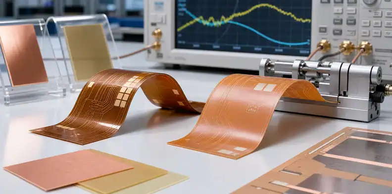
Quick Answer: Choose Pyralux TK when fluoropolymer/polyimide construction and lower high-frequency loss are central to the flex circuit, and choose Pyralux AP when an all-polyimide adhesiveless laminate better fits robust flex or rigid-flex construction. A Pyralux TK vs AP RFQ must compare the complete laminate system—not just Dk and Df—including bondply or coverlay, copper type, dielectric thickness, bend duty, impedance geometry, dimensional behavior, fabrication process, and test evidence.
Pyralux TK vs AP is not a comparison between a “good” and “better” flexible laminate. DuPont designed the two families around different polymer architectures and use cases. TK combines a fluoropolymer dielectric with Kapton polyimide and is available as laminate and bondply for high-frequency flex. AP is an adhesiveless all-polyimide laminate used across demanding flex and rigid-flex builds.
This article owns that material-system decision. It does not repeat the general rigid-flex versus flexible PCB cost decision or a broad polyimide overview. The PCB materials guide remains the entry point when the substrate class itself is unresolved.
Table of Contents
- Define the electrical and bending duty together
- Compare the polymer architectures behind TK and AP
- Select laminate, bondply, and coverlay as one system
- Model copper and thickness instead of copying Dk
- Design bends around the chosen material stack
- Qualify imaging, drilling, bonding, and dimensional control
- Approve substitutions at construction level
- Release a flex RFQ that joins loss and mechanics
Define the electrical and bending duty together
Selection rule: The material must satisfy both the electromagnetic structure and the flex life; neither requirement can be checked after the other is frozen.
Start by classifying the circuit. Is the flex installed once, bent a limited number of times during assembly, or cycled dynamically for its service life? What is the minimum bend radius, bend angle, unsupported length, layer count, copper orientation, and temperature range? On the electrical side, record frequency, impedance, insertion-loss or phase target, route length, launch design, power, and shielding needs.
TK becomes relevant when high-frequency loss and stable dielectric behavior justify a fluoropolymer/polyimide construction. AP can be the more direct choice when an adhesiveless all-polyimide laminate meets the electrical budget and mechanical robustness, processing familiarity, or broad flex construction is more significant. The correct answer can also vary by layer: a hybrid rigid-flex may use a specialty flex material only where the RF route crosses the flexible region.
Create one requirement table rather than separate electrical and mechanical notes:
| Design condition | Required project value |
|---|---|
| Flex duty | Static install, flex-to-install, or dynamic cycles |
| Bend geometry | Radius, angle, bend length, layer count, neutral-axis intent |
| Electrical structure | Microstrip, stripline, coplanar, differential, antenna feed |
| Performance | Frequency, impedance, loss, phase, power, temperature |
| Environment | Moisture, chemicals, vibration, assembly and rework exposure |
This reveals conflicts early. A thicker dielectric may help a preferred RF geometry but increase strain. A low-profile copper option may improve conductor loss but require a specific supply route. A shield film or coverlay can alter both stiffness and effective impedance.
Compare the polymer architectures behind TK and AP
DuPont describes Pyralux TK as a Teflon fluoropolymer and Kapton polyimide composite for high-speed/high-frequency flex applications. The portfolio includes laminate and bondply. Pyralux AP is an adhesiveless, all-polyimide copper-clad laminate, available in a range of dielectric and copper constructions for flexible and rigid-flex circuits.
The architecture changes more than one datasheet number. Fluoropolymer-containing TK can provide attractive high-frequency behavior, while AP’s all-polyimide construction provides a familiar adhesiveless flex platform. Differences can appear in bond systems, thermal expansion, dimensional movement, adhesion preparation, drill/desmear route, coverlay compatibility, and the way finished geometry correlates with the field solver.
Do not infer processing from the brand alone. Ask the fabricator which TK or AP constructions it has qualified, with which copper, adhesive or bondply, coverlay, press cycle, drilling method, and surface treatment. A supplier’s experience with AP does not automatically prove experience with TK bondply.
The product choice should be written as an architecture decision: “TK laminate and named TK bondply for the RF flex region” or “AP adhesiveless laminate with the approved coverlay system.” That statement is far more useful than “use Pyralux.”
Select laminate, bondply, and coverlay as one system
System rule: Approve every dielectric and bonding layer that surrounds the signal; do not specify the copper-clad laminate while leaving bondply and coverlay open.
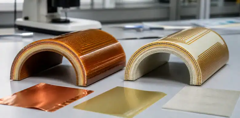
In a multilayer flex or rigid-flex board, the laminate is only part of the dielectric field. Bondply joins layers and flows around copper. Coverlay protects outer conductors and adds dielectric loading and local stiffness. Adhesives, stiffeners, shield films, solder mask in rigid areas, and transition constructions can all influence impedance and bending.
For TK, confirm whether the design uses TK laminate and TK bondply, the exact thicknesses, and the qualified lamination route. For AP, identify the all-polyimide laminate construction and the selected coverlay or adhesive system. If a different DuPont family such as an epoxy-based low-loss companion material is proposed, record it as a separate product with its own function; do not merge its properties into TK or AP.
| System layer | RFQ identity |
|---|---|
| Copper-clad laminate | Family, grade, dielectric thickness, copper type/thickness |
| Bonding dielectric | Product, construction, supplied/pressed thickness, flow basis |
| Coverlay | Film and adhesive thickness, opening tolerance, cured condition |
| Shield or overlay | Product, ground connection, overlap, thickness and loss assumption |
| Stiffener | Material, thickness, adhesive, location and edge transition |
Rigid-flex transition regions require explicit overlap and resin-control dimensions. Use the rigid-flex no-flow prepreg lamination review for the rigid-section bonding and pocket interface; keep the TK/AP callout focused on the flexible material system.
Model copper and thickness instead of copying Dk
Published typical Dk and Df values help screen materials, but the field solver needs the current product-specific method, frequency, dielectric thickness, and supported design value. DuPont’s TK FAQ also warns that comparisons should use the same thickness and that thinner circuits can show a greater proportion of conductor loss.
That warning changes the buying conversation. A thin flex may not realize the full apparent advantage of a lower-loss dielectric if copper roughness, trace width, and skin-effect loss dominate. Conversely, a material with acceptable Df may still fail an RF phase or geometry target if the actual dielectric thickness differs from the model.
Require these model inputs:
| Input | Control needed |
|---|---|
| Dk/Df | Current source, method, frequency, design value |
| Copper | Rolled-annealed or electrodeposited type, thickness, surface/profile |
| Dielectric | Nominal and finished thickness plus tolerance |
| Coverlay/bondply | Cured thickness and dielectric assumption |
| Etch geometry | Top/bottom width, copper thickness, compensation rule |
For controlled lines, tie the stackup to the PCB impedance test report requirements. A coupon must represent the flex material, copper, coverlay, and process; a coupon placed only in a rigid FR-4 panel area cannot validate the flexible RF route.
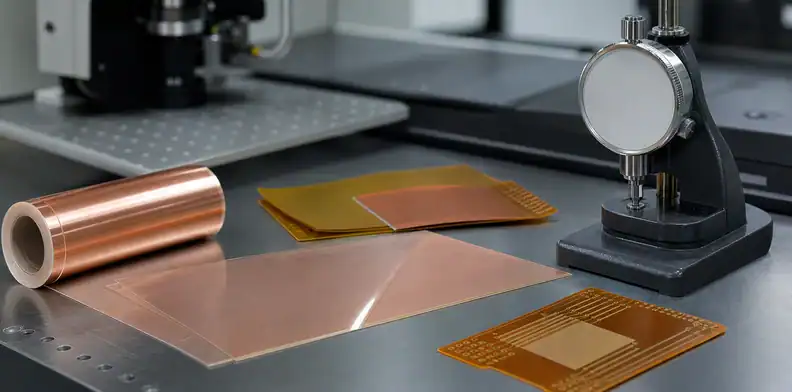
Copper choice is both electrical and mechanical. Rolled-annealed copper is commonly selected for flex endurance, while surface profile and treatment affect conductor loss. Record the exact foil and grain-direction constraints if bend performance depends on them.
Design bends around the chosen material stack
Bend rule: Calculate strain from the finished multilayer construction and keep discontinuities away from the bend, rather than assigning one radius to every Pyralux circuit.
Bend reliability depends on total thickness, neutral-axis location, copper thickness, layer count, material modulus, adhesive layers, coverlay, shield film, stiffeners, trace direction, and cycle count. TK and AP can support flexible circuits, but the accepted radius should come from the actual stack and qualification—not from a generic rule tied to the brand.
Place traces perpendicular to the bend axis where possible and avoid plated holes, component pads, abrupt width changes, coverlay edges, stiffener edges, and rigid-flex transitions inside the active bend. Use curved routing and staggered conductors where the design and impedance permit. Dynamic designs need a more conservative construction and representative cycle testing than a flex-to-install cable.
The flex PCB stiffener requirements page controls stiffener material, adhesive, edge treatment, registration, and connector support. In the TK/AP RFQ, identify how that stiffener changes the local electrical launch and where its edge sits relative to the bend.
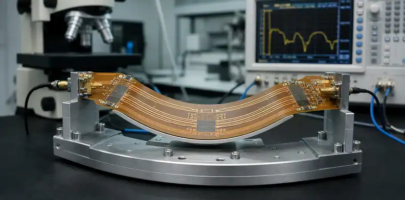
Dynamic flex qualification must reproduce the assembled boundary conditions. A loose strip bent around a mandrel is useful for screening, but it may not represent a cable constrained by connectors, shields, adhesive, enclosure guides, or a moving carriage. Define the fixture, stroke, rate, radius, dwell, temperature, and electrical monitoring. Decide whether failure means an open circuit, resistance change, impedance drift, visible crack, delamination, or loss shift.
The artwork review should protect copper where strain concentrates. Teardrops, curved transitions, staggered traces, balanced copper, and gradual stiffener edges can help when they fit the RF geometry. However, an automatic fillet or copper-balancing change near a controlled line can alter impedance. Mark bend and RF zones so CAM knows which changes need engineering approval.
| Bend variable | Evidence before release |
|---|---|
| Finished flex thickness | Supplier stackup and measured first article |
| Minimum radius and cycles | Drawing plus representative bend test |
| Copper orientation | Artwork and foil direction record where required |
| Discontinuity clearance | Fabrication drawing and CAM check |
Qualify imaging, drilling, bonding, and dimensional control
High-frequency flex quality depends on more than material certificates. Review the supplier’s process for storage, cleaning, imaging, etching, surface preparation, drilling or laser processing, desmear, plating, coverlay registration, lamination, dimensional compensation, routing, and final handling.
TK’s fluoropolymer-containing system may require process controls different from an all-polyimide AP construction. Do not prescribe chemistry from an unrelated PTFE rigid-board article; ask the qualified fabricator to document the material-specific route and evidence. The buyer needs proof of capability, not a copied process recipe.
First-article inspection should measure critical line geometry, dielectric and coverlay thickness, layer registration, finished outline, stiffener position, plated-hole quality where applicable, impedance, and the chosen RF metric. Add bend testing that represents the real radius, fixture, cycles, and temperature. Cosmetic inspection should include wrinkles, delamination, dents, coverlay voids, adhesive squeeze-out, and handling damage with defined acceptance criteria.
If the board includes rigid-flex transitions, microsections should cross the interfaces and holes most likely to reveal resin or plating problems. Lot traceability should identify the laminate, bondply, coverlay, copper, and critical process revision.
Dimensional compensation deserves a dedicated first-article check. Flexible films can move through imaging, etching, coverlay cure, and lamination. Measure fiducials, connector features, RF line widths/gaps, coverlay openings, stiffener registration, and finished outline against the same datum scheme used by assembly. A board can pass electrical test in a flat coupon yet fail installation because accumulated registration error moves a connector or exposes copper at a coverlay edge.
Handling and packaging are part of the production route. Define panel or unit support, bend protection, separator materials, moisture controls where required, inspection lighting, and shipment orientation. Thin TK or AP circuits can be creased or dented after they pass fabrication. The outgoing inspection record should distinguish process defects from shipping damage and preserve representative photographs for the lot.
Approve substitutions at construction level
Change rule: A substitute is not equivalent until the complete electrical, mechanical, process, and supply impact has been accepted for the named construction.
An AP proposal cannot replace TK merely because both are Pyralux. A different TK thickness or copper is also a change. Compare architecture, Dk/Df basis, dielectric thickness, bondply/coverlay, copper, bend behavior, thermal properties, dimensional stability, process route, availability, and qualification evidence.
Use PCB material substitution approval to name affected part numbers, stackup revision, lots, model updates, bend tests, RF tests, process evidence, approvers, and temporary or permanent scope. For customer-controlled RF products, determine whether the customer must approve before fabrication.
Schedule pressure should be visible. Ask for MOQ, lead time, standard constructions, and regional source during quotation. If the preferred TK bondply is unavailable, evaluate whether redesigning around AP, another TK construction, or a different material is technically and commercially justified. Do not allow the fabricator to solve availability through an undisclosed bonding film.
Receiving and travelers should trace all components of the material system. The laminate name alone cannot prove that the approved coverlay, bondply, or copper entered the lot.
When a substitute is approved, update every dependent record: field-solver library, controlled stackup, drawing notes, purchasing item, receiving criteria, traveler, coupon artwork, bend-test plan, and customer documentation. Leaving the old material in one system creates a split baseline in which purchasing, engineering, and quality believe they approved different constructions. The change notice should identify the effective lot and disposition of remaining inventory.
Release a flex RFQ that joins loss and mechanics
The released package should contain native artwork, fabrication drawing, netlist, layer map, complete flexible and rigid stackups, material-system identities, impedance/RF geometry, bend zones and radii, copper direction where controlled, coverlay openings, stiffeners, shield details, hole/slot table, surface finish, coupon plans, quantities, acceptance criteria, and approval contacts.
Require a returned supplier stackup and exception list. The response should identify TK or AP constructions, bondply/coverlay, copper, pressed thickness, Dk/Df assumptions, geometry changes, bend capability, process route, evidence, lead time, MOQ, and every alternate.
Keep two baselines together: the electromagnetic model and the mechanical flex definition. A supplier change that preserves impedance but moves a stiffener edge or thickens the flex can still fail. A change that improves bend strain but alters phase length also needs review.
Send the complete package through the QueenEMS contact page for flex fabrication review. QueenEMS can return construction, transition, coupon, and evidence questions before the design is locked into a material system.
Release decision: Use TK or AP only after one approved stackup proves the required RF behavior, bend duty, fabrication route, and supply identity together.
FAQ
Is Pyralux TK always lower loss than Pyralux AP?
TK is designed for high-speed/high-frequency flex and uses a fluoropolymer/polyimide construction, but finished loss depends on thickness, copper, geometry, coverlay, launches, and test method. Compare the exact proposed systems.
Can AP use TK bondply?
Do not assume compatibility from the shared Pyralux brand. Ask DuPont and the qualified fabricator for the approved material combination, process route, and evidence for the exact stackup.
Does a material datasheet define the minimum bend radius?
No. Bend radius and life depend on the finished construction, copper, layer count, discontinuities, and cycle duty. Specify and test the actual flex design.
Should the impedance coupon be in the rigid panel area?
Not if it is intended to validate a TK or AP flexible RF route. The coupon must reproduce the relevant dielectric, copper, coverlay, geometry, and process.
Sources
- DuPont, Pyralux laminates
- DuPont, Pyralux TK frequently asked questions
Written by the QueenEMS Engineering Team
Upload your files today · Free DFM check before production · Ship worldwide
Get your PCB prototypes in as fast as 24 hours. We handle FR4, Rogers, and hybrid boards up to 40 layers in volume production, with advanced builds subject to engineering review — free prototypes for 2–4 layer FR-4 boards, no minimum order.
Just upload your Gerber + BOM — we source every part, assemble, and inspect (AOI + X‑Ray) so you don't have to chase suppliers. Boards ship in as fast as 24 hours.