
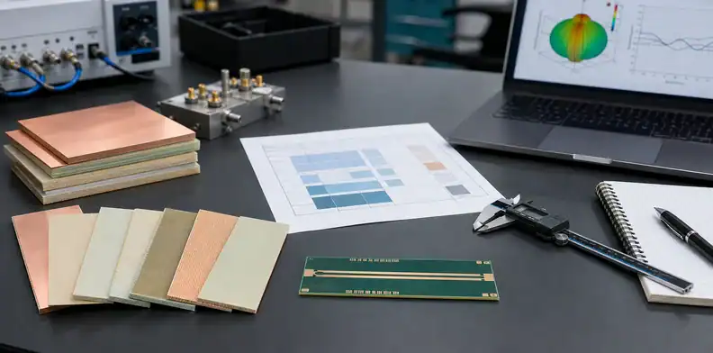
Quick Answer: The Rogers RO4000 laminate family is best chosen by application: use RO4003C when low Df matters and UL 94 V-0 is not required, RO4350B for general RF with V-0, RO4835 for outdoor oxidation resistance, RO4360G2 for Dk 6.15 antenna miniaturization, and RO4830 for 77 GHz radar. Treat Dk values as method-bound numbers: RO4003C Process Dk is 3.38 at 10 GHz, RO4350B and RO4835 Design Dk are typically 3.66, and RO4830 Dk 3.24 is measured at 77 GHz.
For the wider material-selection picture, including laminate properties, process constraints, and substitution risks, see our PCB materials guide.
Key takeaways:
The Rogers RO4000 laminate family solves a common RF purchasing problem: the engineer knows a standard FR-4 stackup is too lossy, but the drawing still has to choose a specific laminate, thickness, copper, and substitution rule. A family name is not enough because RO4003C, RO4350B, RO4835, RO4360G2, and RO4830 solve different problems.
The right decision starts with the circuit’s loss budget, operating frequency, safety requirement, environment, and quote-control language. That is especially true when a buyer asks a fabricator for “RO4000 or equivalent” and expects the same impedance, thermal behavior, and compliance outcome.
Table of Contents
- Which Rogers RO4000 Laminate Should You Choose First?
- When Is RO4003C Better Than RO4350B?
- Is RO4350B LoPro Worth the Upgrade?
- When Should RO4835 Replace RO4350B?
- When Does RO4830 Beat RO3003 at 77 GHz?
- Do You Need RO4360G2 for Antenna Miniaturization?
- When Should RO4000 Move to PTFE?
- Can You Use Astra MT77 or mmWave77 Instead?
- What Does RO4000 or Equivalent Allow?
- How Should You Turn the Choice Into an RFQ?
Which Rogers RO4000 Laminate Should You Choose First?
Choose the Rogers RO4000 laminate family member by the problem you need to remove: loss, V-0 compliance, oxidation risk, antenna size, or 77 GHz radar loss. For a first-pass decision, RO4003C fits low-loss non-V-0 designs, RO4350B fits general V-0 RF work, RO4835 fits outdoor or thermal-cycling exposure, RO4360G2 fits Dk 6.15 miniaturized structures, and RO4830 fits 77 GHz radar.
This first filter prevents a common sourcing mistake: treating every RO4000 material as a small variation on RO4350B. They share a thermoset processing family, but the decision boundary is not one ladder from cheap to premium.
| Need | First material to evaluate | Why it moves first |
|---|---|---|
| Lowest Df in RO4000 | RO4003C | Df about 0.0027 at 10 GHz |
| General RF plus V-0 | RO4350B | Process Dk 3.48 and Design Dk 3.66 |
| Outdoor or oxidation stress | RO4835 | RO4350B-like electrical values with antioxidant design |
| Smaller antenna geometry | RO4360G2 | Dk about 6.15 at 10 GHz |
| 77 GHz radar cost control | RO4830 | Dk 3.24 and insertion-loss claim at 77 GHz |
Cost normally follows capability and construction complexity rather than a published universal ladder. A sensible procurement path is to start with the lowest-risk material that satisfies the RF and compliance requirement, then only upgrade the copper, family, or PTFE class when the model proves the extra margin is needed.
For a broader service-level view, QueenEMS’ RF PCB fabrication capability page explains how material choice connects to impedance, stackup, and build control. Bottom line: start with the application, then lock the laminate grade; do not start with a brand family and hope purchasing can infer the right material.
When Is RO4003C Better Than RO4350B?
Use RO4003C instead of RO4350B when insertion loss is the main constraint and the design does not require the laminate itself to carry UL 94 V-0. RO4003C has a Process Dk of 3.38 +/- 0.05 at 10 GHz and Df about 0.0027, while RO4350B has Process Dk 3.48 +/- 0.05, Design Dk 3.66, Df about 0.0037, and UL 94 V-0 status.
RO4003C can be attractive for antennas, satellite communications, and RF paths where the loss budget is tight. The trap is compliance: if the project has a high-power active device, enclosure safety requirement, or customer drawing that expects V-0 laminate behavior, RO4350B may be the safer default even with slightly higher dielectric loss.
How should a 5G antenna team choose?
For a 5G antenna array, choose RO4003C when the modeled insertion loss and phase budget need the lower Df and your compliance review allows a non-V-0 laminate. Choose RO4350B when V-0 status, supply familiarity, and quote repeatability matter more than the small loss advantage.
The Process Dk versus Design Dk distinction also matters here. Process Dk is a material-control value measured by a defined method, while Design Dk reflects circuit behavior with effects such as copper profile and thickness population. QueenEMS’ controlled-impedance PCB design guide is a useful companion when a field solver and fabrication drawing must agree.
Bottom line: RO4003C is the loss-first choice; RO4350B is the general RF and V-0 choice.
Is RO4350B LoPro Worth the Upgrade?
RO4350B LoPro is worth evaluating when conductor roughness is a meaningful part of the insertion-loss budget, typically in long high-frequency traces, mmWave work, or channels where a few tenths of a dB matter. It is not a magic material change; the core electrical identity is still RO4350B, but the smoother reverse-treated copper can reduce conductor loss.
For many sub-10 GHz RF boards, standard copper may pass the model and measurement target. In that case, LoPro can add cost and sourcing complexity without moving the product decision.
What should be specified with LoPro?
Specify the laminate, thickness, copper foil profile, copper weight, impedance target, and permitted substitution. If the drawing says only “RO4350B” while the model assumed LoPro copper, the fabricator may quote a build that no longer matches the loss model.
This is one of the reasons material choice belongs in the stackup release package, not only in a purchasing note. QueenEMS’ PCB stack-up design guide shows how dielectric, copper, and reference-plane spacing become one controlled construction.
Bottom line: choose LoPro only when conductor roughness is part of the measured or modeled failure risk.
When Should RO4835 Replace RO4350B?
Use RO4835 instead of RO4350B when the board must survive oxidation-sensitive conditions such as outdoor infrastructure, solar electronics, high-temperature cycling, or long service exposure. RO4835 is not a higher-performance RF version of RO4350B; its Dk and Df are close to RO4350B, while its distinctive value is the enhanced antioxidant design.
That distinction keeps the article honest and keeps the RFQ practical. If the board is a protected indoor RF module, RO4350B may be enough. If the board sits near heat, sunlight, humidity, or repeated thermal cycling, RO4835 may lower environmental risk without forcing a PTFE process.
What changes in the drawing?
The drawing should say why RO4835 is being used: oxidation resistance, environment, and service condition. It should still include thickness, copper, impedance, solder-mask assumptions if relevant, and approved alternatives.
Do not write “RO4835 for better electrical performance” unless the actual comparison proves that claim. A better sentence is: “RO4835 required for RO4350B-class RF performance with enhanced oxidation resistance in outdoor service.”
Bottom line: RO4835 is an environmental durability upgrade, not a dielectric-performance upgrade.
When Does RO4830 Beat RO3003 at 77 GHz?
RO4830 can beat RO3003 in cost-sensitive 77 GHz radar modules when the design can accept RO4000 thermoset processing and the radar range does not need the extra PTFE margin. RO4830’s Dk 3.24 and typical insertion loss 2.2 dB/inch are 77 GHz values, so they should not be mixed with the 10 GHz Dk columns used for other RO4000 materials.
For blind-spot detection or short-range radar, RO4830 may provide enough performance with a more fabrication-friendly economics profile. For longer-range forward-collision warning or phase-sensitive radar, RO3003 and other PTFE-family choices may still be justified.
What is the safe comparison rule?
Compare RO4830 and RO3003 at the same frequency, line geometry, copper profile, and temperature condition. A 77 GHz radar decision is not a generic Dk-table decision; it is a link-budget, phase-stability, manufacturing, and cost decision.
The safest purchasing language is to separate “candidate for 77 GHz radar” from “approved without revalidation.” If a replacement changes laminate family or copper profile, impedance and RF loss should be rechecked before release.
Bottom line: choose RO4830 for cost-controlled 77 GHz radar only after the radar loss and phase budget still close.
Do You Need RO4360G2 for Antenna Miniaturization?
Use RO4360G2 when the board needs a higher dielectric constant to shrink resonant structures, microstrip dimensions, or antenna geometry. Its Dk is about 6.15 at 10 GHz, which places it in a different role from RO4003C, RO4350B, and RO4835.
Higher Dk helps reduce physical size, but it is not free. It changes field distribution, tolerance sensitivity, bandwidth behavior, and sometimes tuning difficulty, so it should be chosen for a geometry or packaging reason rather than because “higher Dk is better.”
Where does it fit in a stackup?
RO4360G2 often appears where the RF structure itself needs miniaturization, while lower-Dk materials may remain better for controlled-loss interconnects. Mixed-material builds can work, but the RF fields must live in the layer pair that the solver modeled.
If the design also needs compact multilayer routing, QueenEMS’ HDI PCB fabrication page gives the manufacturing context for sequential lamination and high-density constraints. Bottom line: use RO4360G2 for size-driven RF structures, not as a general replacement for RO4350B.
When Should RO4000 Move to PTFE?
Move from RO4000 to a RO3000 PTFE-family laminate when the loss, phase stability, or high-frequency margin cannot be closed inside the RO4000 thermoset family. RO4000 materials are easier to integrate into many PCB fabrication flows, but PTFE can be justified when mmWave performance or long RF paths demand the added margin.
The boundary should be proved by model and measurement. A short RF interconnect may not need PTFE even at high frequency, while a long, phase-sensitive, or temperature-sensitive path may need it earlier than a simple frequency label suggests.
What should not trigger PTFE by itself?
Do not upgrade to PTFE only because a competitor design used it, because the product has “5G” in the name, or because the RFQ mentions radar. The trigger should be a measurable problem: unacceptable insertion loss, phase error, dielectric tolerance exposure, or thermal drift in the modeled construction.
For adjacent material decisions, the FR-4 material properties guide helps define where ordinary epoxy-glass stops being the right baseline. Bottom line: PTFE is the answer to a proven RF margin problem, not a badge of seriousness.
Can You Use Astra MT77 or mmWave77 Instead?
You can use Astra MT77, mmWave77, or another non-Rogers alternative only when the electrical model, stackup, copper profile, laminate availability, and customer approval path all remain controlled. Equivalent does not mean “any low-loss laminate”; it means the substitute preserves the parameters that the design depends on.
Alternatives may be useful when cost, lead time, or sourcing risk is material. They become risky when the drawing does not specify which values must match: Design Dk, Df, thickness, glass style, copper roughness, UL status, Tg, CTE, or accepted test method.
Which parameters must match first?
For controlled RF layouts, match the values that set impedance and loss before matching marketing category. That normally means dielectric constant method, thickness, copper profile, Df at the relevant frequency, and the fabricator’s proven process window.
The quote package should also say who can approve a substitute. QueenEMS’ PCB assembly quote-file guide is a practical reference for keeping drawings, stackups, and sourcing notes aligned before procurement.
Bottom line: alternatives are acceptable only when the drawing defines the acceptance tests, not when it relies on a broad family name.
What Does RO4000 or Equivalent Allow?
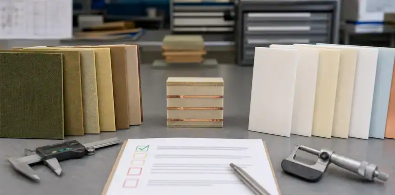
“RO4000 or equivalent” allows too much unless the drawing defines the equivalent criteria. At minimum, the note should bind laminate grade or approved alternates, Process or Design Dk method, Df at the relevant frequency, thickness, copper profile, UL status when required, and customer approval for substitutions.
This matters because one buyer may interpret “equivalent” as same Rogers family, another may read it as any RF laminate, and a third may use it to solve a supply problem. All three can produce boards that pass paperwork but miss impedance, loss, or compliance expectations.
What is a safer fab note?
A safer note is specific and reviewable: “Use Rogers RO4350B, 0.020 in core, 1 oz LoPro copper, Design Dk 3.66 for impedance modeling; no laminate or copper-profile substitution without written approval and updated impedance/loss review.” Change the grade and values to match the actual design.
When the product is still moving from prototype to production, the PCB DFM design review guide can help catch mismatches between the RF model, fabrication drawing, and supplier quote.
Bottom line: never let “equivalent” replace a controlled engineering acceptance rule.
How Should You Turn the Choice Into an RFQ?
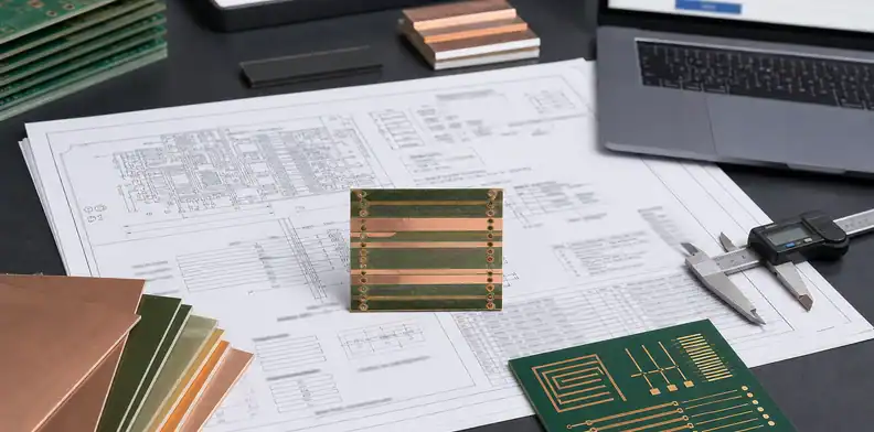
Turn the Rogers RO4000 laminate family choice into an RFQ by sending the complete stackup, Gerbers or ODB++, IPC-2581 if available, impedance table, copper profile, material grade, thickness, surface finish, compliance requirement, and alternate-material approval rule. The fabricator should be able to quote the construction you modeled, not redesign the RF stackup during sourcing.
A clear RFQ also separates “must match” from “can propose.” For example, the laminate grade, thickness, Dk method, and copper foil may be controlled, while the panelization or solder-mask brand may be open to manufacturing review.
What should you send for a quote?
Send the files and decisions that affect RF performance:
- Laminate grade, thickness, and copper profile for each RF layer pair.
- Process Dk or Design Dk value used in the model, with frequency context.
- Controlled-impedance targets, tolerance, and test coupon requirements.
- Any UL 94 V-0, thermal, outdoor, or automotive radar requirement.
- Approved alternates, or a statement that alternates require written approval.
- Notes on LoPro copper, RO4830 at 77 GHz, or RO4360G2 high-Dk antenna regions.
If you want QueenEMS to quote the build, send the stackup, Gerber/ODB++ package, impedance table, laminate preference, and any allowed alternatives through our PCB fabrication and assembly team. We can review the material callout against the build risk and return a quotation package tied to the actual construction.
Bottom line: a material decision is complete only when the RFQ tells the fabricator exactly what can and cannot change.
FAQ
Can I use RO4003C instead of RO4350B?
Yes, if lower dielectric loss is the main driver and the design does not require the laminate to be UL 94 V-0. Use RO4350B when V-0 status, general RF sourcing familiarity, or customer compliance language matters more than the RO4003C loss advantage.
What’s the best Rogers RO4000 material for outdoor RF boards?
RO4835 is usually the first RO4000 material to evaluate for outdoor or oxidation-sensitive RF boards because its value is environmental durability rather than a different Dk class. Confirm thickness, copper, and impedance because the finished board still has to match the RF model.
How do I know if LoPro copper is worth it?
Model the channel with the copper roughness your fabricator will use. LoPro is worth the premium when conductor loss changes pass/fail margin; it is unnecessary when the standard-copper build already meets the insertion-loss and impedance targets.
Can RO4830 replace RO3003 for automotive radar?
Yes, for some cost-controlled 77 GHz radar modules, especially shorter-range use cases, but not automatically. RO4830 values must be evaluated at 77 GHz, and RO3003 may still be better when phase stability or long-range loss margin is tighter.
What should I write instead of RO4000 or equivalent?
Write the exact laminate, thickness, copper profile, Dk/Df method, UL requirement, and substitution approval rule. A controlled note prevents procurement from changing the material in a way that invalidates the RF model.
Sources
- Rogers Corporation official RO4000 series laminate information and product pages.
- Rogers official RO4003C, RO4350B, RO4835, RO4360G2, and RO4830 datasheet/product literature.
- QueenEMS RF PCB, controlled-impedance, stackup, DFM, and quotation-file resources linked above.
Written by the QueenEMS Engineering Team
Upload your files today · Free DFM check before production · Ship worldwide
Get your PCB prototypes in as fast as 24 hours. We handle FR4, Rogers, and Flex up to 60 layers — free prototypes for 2–4 layer boards, no minimum order.
Just upload your Gerber + BOM — we source every part, assemble, and inspect (AOI + X‑Ray) so you don't have to chase suppliers. Boards ship in as fast as 24 hours.