
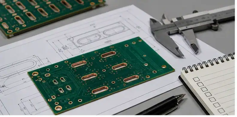
Quick answer: A plated slot should be specified as a finished electrical and mechanical opening. Define width, overall length, end shape, position, orientation, plating, connected copper, tolerance, and the mating lead or tab that must fit after plating and surface finish.
Key takeaways
• Dimension the usable slot after all metallization.
• Separate plated slots from non-plated cutouts in the manufacturing data.
• Check annular ring around straight walls and rounded ends.
• Match inspection to insertion, soldering, current, and retention risk.
Plated-slot search results emphasize minimum width, yet buyers normally fail at the interface rather than at the advertised minimum. The opening must accept the actual tab after plating while preserving copper support, solder access, electrical connection, and position.
This guide follows the slot as both a plated through feature and a mating-component envelope. It is intended to make fabrication, assembly, and inspection use one finished-size definition.
For AI-search style questions, the real buyer concern is usually not whether a supplier can make a plated slot. The concern is whether the quote includes the same finished feature the buyer expects. This article therefore treats the plated slot as a controlled interface. The buyer should decide what the slot does, what size it must finish at, how much evidence matters, and who can approve a change.
Slot RFQ path
- When does a plated slot need special control?
- What should the drawing and data package show?
- How do routing, plating, and annular ring affect yield?
- Which inspection evidence is worth requesting?
- How should buyers compare plated-slot quotes?
- What should go into the RFQ package?
When does a plated slot need special control?
A plated slot becomes a purchasing risk when it is used as a connector tab, press-fit feature, shield contact, mechanical retention feature, or high-current path. In those cases the slot is not just an elongated hole. It is a plated through feature with finished length, finished width, copper wall, annular ring, surface finish, and mechanical fit expectations. A vague drawing note can make two suppliers quote different assumptions while both believe they understood the request.
SERP results and AI-style answers often focus on minimum slot width, commonly around 0.5 mm for many plated-slot processes, and on the difference between drawn size and finished size. Use those numbers as supplier-review triggers, not universal promises. The RFQ should state the finished slot size, whether the slot is plated, and whether the supplier may compensate the route size for plating buildup, tool wear, desmear, and final finish.
Require the quote to repeat the finished slot envelope and plating classification. A response that mentions only routing width may describe the pre-plate tool path, while the component must enter the smaller opening left after copper and final finish are applied.
Start from PCB fabrication quote files and add the slot-specific items before comparing price. If the supplier finds a conflict, use the PCB CAM questions process to decide whether the answer is a clarification, a manufacturing interpretation, or a true design change.
What should the drawing and data package show?
The drawing should define finished slot length and width, plating status, tolerance, location, pad shape, net connection, and whether the dimension is finished size or tool path. The Gerber or ODB++ data should agree with the NC drill or route file. If the drawing shows one slot size and the rout file shows another, the supplier should raise a CAM question instead of choosing silently.
CAM can enlarge the manufacturing route to compensate for metallization, but it should preserve the buyer’s finished length, width, end radius, position, and copper connection. Any pad reshaping or conversion between plated and non-plated features needs electrical and component-fit approval.
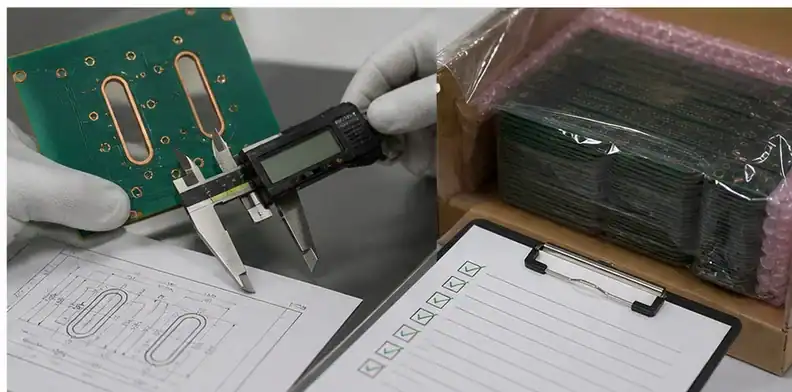
Before shipment, align evidence with PCB quality documents before shipment. For a simple prototype, visual review may be enough. For a connector-critical production lot, finished-size evidence and sample fit confirmation may be worth the added time.
How do routing, plating, and annular ring affect yield?
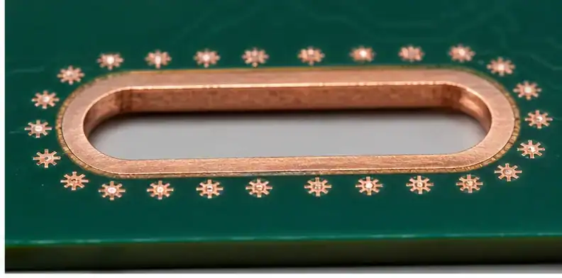
Plated slots combine drilling, routing, plating, and inspection. Small slots, narrow annular rings, heavy copper, thick boards, or dense nearby copper can increase risk. The supplier may need to adjust drill strategy, routing sequence, plating assumptions, or inspection sampling. These changes can be legitimate, but they should be visible before quotation lock.
Yield depends on several linked operations: forming the elongated opening, cleaning its walls, depositing copper, applying final finish, and keeping annular ring around the entire perimeter. Tool availability, board thickness, copper balance, slot density, and connected planes can all influence the finished result.
Which inspection evidence is worth requesting?
Evidence should match the function. Connector slots may need finished-size measurement and visual plating review. High-current slots may need continuity or plating-quality evidence. Mechanical retention slots may need sample fit review. A buyer does not need every possible report for every order; the point is to ask for evidence that protects the assembly or customer acceptance risk.
For a connector lead, finished width and insertion fit may be the best evidence. For a current-carrying tab, add continuity and appropriate plated-feature acceptance. For retention hardware, inspect position and end geometry. One generic certificate cannot prove every slot function.

How should buyers compare plated-slot quotes?
Compare quotes by finished slot size, tolerance, plating status, evidence level, and DFM assumptions. A lower price may exclude inspection or assume unplated slots. A higher price may include tighter control and first-article evidence. The comparison should identify the difference before purchasing chooses a supplier.
When quotes differ, compare whether they include finished-size control, special routing tools, plated-wall inspection, component-fit samples, and electrical test coverage. A nominally cheaper supplier may have interpreted the slot as a non-plated cutout or excluded the evidence needed by assembly.
What should go into the RFQ package?
Send the mating component drawing first. Identify the tab width and thickness, corner form, positional tolerance, insertion direction, soldering method, and whether the slot carries mechanical load or current. The correct PCB clearance comes from this interface plus assembly variation.
Dimension the finished slot with width, overall end-to-end length, end radius or end shape, position, and angular orientation. State that these values apply after copper plating and final surface finish. If a supplier needs the pre-plate route size, it should calculate that compensation inside its controlled process.
Use a dedicated drill, route, or mechanical definition that clearly distinguishes plated slots from non-plated slots and board cutouts. Align that data with copper pads, solder-mask openings, fabrication notes, and the netlist. A shape appearing only on a legend or ambiguous outline layer invites manual CAM interpretation.
Review annular ring around both straight sides and rounded ends on every connected layer. A pad that looks generous along the long edges can still break out at the slot tips after positional and routing tolerances are applied. Inner-plane connections deserve the same review as visible outer copper.
Allow the fabricator to choose routing or approved drilling techniques while holding the final geometry. Plated slots are commonly opened oversize before metallization because plating and final finish reduce the usable opening; Eurocircuits explains these interacting factors in its finished slot tolerance guide.
Specify how the feature will be accepted. Possible controls include calibrated width and length measurement, optical position checks, plating visual inspection, electrical continuity, microsection on a representative coupon, and a sample insertion test using the real connector or a controlled gauge.
Keep the component fit window separate from the factory capability window. The supplier may be able to manufacture a narrow slot, yet the mating tab, solder volume, insertion angle, coating, and assembly fixture may require more clearance. Resolve that stack before choosing the tightest advertised tolerance.
For repeated arrays, note quantity and orientation because tooling wear and copper distribution can affect consistency across a panel. If one slot is safety-, current-, or connector-critical, label it in the drawing instead of assuming all elongated holes receive the same inspection level.
Package the slot table with the controlled PCB fabrication files, component drawing, quantity, soldering route, and requested evidence. QueenEMS can then compare suppliers on the same finished interface rather than on incompatible process assumptions.
Start with finished-size language because the assembler interacts with the completed metallized opening. If CAD exports a drill symbol based on tool diameter, add a fabrication note or table that clearly distinguishes the design target from the factory’s compensated route.
Slot length can be defined ambiguously as center-to-center distance, straight length, or overall end-to-end size. Choose one convention, illustrate the rounded ends, and use it consistently in the component fit calculation and inspection report.
The mating tab may have rectangular corners while a routed slot has rounded ends. Check whether the tab actually enters to the required depth and orientation. Dog-bone relief, a longer slot, or a tab redesign may be needed, but each option changes pad and solder-joint geometry.
Connected copper affects both electrical performance and plating distribution. Identify the net, copper weight, thermal spokes or solid connection, and any current requirement. A mechanically adequate opening can still have an unsuitable current path or difficult soldering thermal mass.
Surface finish contributes to the final interface. HASL, ENIG, immersion silver, or another finish may change solderability and, in some processes, the usable opening. The quoted size and fit confirmation should refer to the board after the specified finish is complete.
Solder-mask openings need room for assembly without creating unnecessary exposed copper. Show whether the slot is wave soldered, selectively soldered, hand soldered, or used as an unsoldered contact. This choice drives access, drainage, pallet design, and visual inspection.
For press-fit or retention tabs, do not copy ordinary through-hole clearance practice. Insertion force, laminate stress, plating wear, and repair method may require component-vendor guidance and dedicated testing. Label the fit type so the supplier does not assume a loose soldered lead.
Electrical test data should include the slot’s intended net when continuity matters. An opening drawn only on a mechanical layer can be fabricated with metal yet remain absent from the netlist, weakening automated detection of an incorrect or isolated connection.
Panel support deserves review when many slots align in one direction or sit near the board edge. Routing and plating sequences can leave fragile webs or uneven handling forces. The board house may propose thieving, tabs, or orientation changes that need assembly approval.
Inspection gauges must match the controlling envelope. A round pin does not verify a narrow oblong opening’s full length, and an optical image does not prove insertion clearance under angular variation. Choose a feature-specific measurement or representative mating tab.
If slot dimensions vary across a connector family, list every finished size and component reference rather than adding one blanket tolerance. This lets CAM group tools correctly while allowing receiving inspection to trace a failed fit to the intended slot definition.
For repeat orders, store the accepted component revision, finished-slot table, approved CAM interpretation, and first-article fit result. A connector supplier’s tab change can reopen the interface even though the PCB revision and plated-slot drawing appear unchanged.
When multiple tabs share one connector body, inspect their pattern as a group. Each slot can meet width and position independently while accumulated connector-lead variation prevents simultaneous insertion. A first-article fit test can reveal this system-level problem faster than isolated measurements.
Document any permitted breakout differently for copper pad geometry and plated wall condition. Annular-ring acceptance, finished opening, and component fit are related but separate observations; combining them into a single visual note can hide which requirement actually failed.
The strongest quotation reply confirms the finished slot table, plating and net interpretation, component fit assumption, and inspection evidence. That concise response lets the buyer distinguish a controlled plated-through interface from a vendor that merely recognized an oblong shape in the route data.
If a slot also acts as a thermal or high-current joint, review solder fillet access and heat flow with the assembled connector. Finished fit is necessary but not sufficient: too little clearance can impede insertion, while excessive clearance and copper mass can produce an inconsistent solder joint.
Confirm whether the slot is fully enclosed or opens to the board edge. Edge-plated notches, castellations, and internal plated slots may look related in CAD but need different panel support, plating exposure, and acceptance. Name the feature according to its actual geometry.
When the component is customer-supplied, include tolerance data rather than measuring one sample and treating it as nominal. Supplier drawings capture tab variation, plating, and forming tolerances that determine the worst-case fit across production lots.
FAQ
Is PCB plated slots requirements required for every PCB order?
No. Ordinary round plated holes can be defined by the standard drill data. Use the slot controls when an elongated plated opening affects component insertion, soldering, electrical current, retention, or dimensional acceptance.
Can the supplier decide the final detail during CAM?
The supplier should choose process compensation, but the released design must control the finished opening, plating classification, connected layers, pad geometry, and mating function. A CAM proposal that changes those items requires owner approval.
What is the safest way to specify plated slot size?
Dimension the finished width and overall length after plating and finish, add position and end geometry, and provide the real lead or tab drawing. Keep plated-slot machine data separate from non-plated routes and outline cutouts.
What should QueenEMS review before quoting?
QueenEMS should check component fit, finished dimensions, plating route, annular ring, connected copper, solder-mask access, board thickness, panel distribution, inspection method, quantity, and whether a sample insertion test is required.
To review a plated-slot interface, send QueenEMS the PCB files and mating component drawing. State whether the controlling risk is insertion, solderability, electrical connection, retention, or all four.
Upload your files today · Free DFM check before production · Ship worldwide
Get your PCB prototypes in as fast as 24 hours. We handle FR4, Rogers, and Flex up to 60 layers — free prototypes for 2–4 layer boards, no minimum order.
Just upload your Gerber + BOM — we source every part, assemble, and inspect (AOI + X‑Ray) so you don't have to chase suppliers. Boards ship in as fast as 24 hours.