
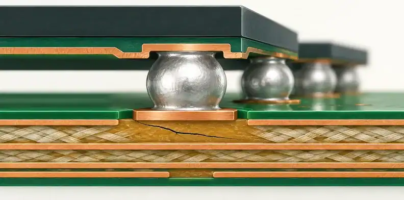
Quick Answer: Pad cratering is a fracture in the PCB dielectric beneath a component land, often associated with the corners of a ball grid array (BGA). An early crack can exist while the electrical connection still works. Confirm the fracture location, preserve specimens before rework, and compare matched samples around the suspected operation. Prevention then depends on reducing the relevant loading or improving the qualified land-and-laminate construction, followed by physical verification.
Pad cratering can turn an apparently sound BGA assembly into a difficult failure investigation. Replacing the component may restore a connection without resolving damage underneath its lands, while a passing inspection can leave the first crack unexplained.
The investigation needs to connect two observations: where the material fractured and what happened to the assembly before that fracture was found. The following approach keeps those questions separate until the evidence supports a connection.
Table of Contents
- Recognize Pad Cratering by Its Fracture Location
- Why a Passing Test Can Miss Early Laminate Cracks
- Trace the Loads in the Assembly Sequence
- Preserve Samples Before Rework or Destructive Analysis
- Choose Evidence That Locates the Fracture
- Compare Samples Across the Suspect Operation
- Connect Pad Strength Tests with Production Strain
- Match the Corrective Action to the Confirmed Damage
- Build a Failure Record Another Engineer Can Check
- Verify the Change on the Released Board Configuration
Recognize Pad Cratering by Its Fracture Location
Identify pad cratering from damage beneath the copper land, rather than from the appearance of a detached pad alone. The crack can run through resin or along its interface with glass reinforcement. A separated land may carry dielectric material with it; mixed damage can also include a broken conductor or solder interface.
| Observed failure | Location to establish | Evidence to examine |
|---|---|---|
| Pad cratering | Dielectric immediately beneath or around the land | Fractured resin, glass-interface separation and the matching board surface |
| Copper foil separation | Copper-to-dielectric bond | Underside of the foil and the exposed bonding surface |
| Solder or intermetallic fracture | Within the joint or its metallurgical interface | Both mating fracture surfaces and a targeted section |
| Trace fracture | Copper conductor, including the land connection | The broken trace and its relationship to the affected pad |
| Broader delamination | Separation within the board construction | Extent through surrounding laminate and the affected layer interfaces |
A copper peel-strength assessment answers an adhesion question. Its result cannot, by itself, identify the fracture in an assembled BGA. The specimen geometry and loading are different, and several damage modes may coexist at one site.
Likewise, visible bubbling or separation across a wider board region calls for a PCB delamination investigation. Keep the original failure descriptions until the laboratory identifies the fracture path. Calling every missing pad a crater can send the corrective action toward the wrong material interface.
Why a Passing Test Can Miss Early Laminate Cracks
A dielectric crack can start before it interrupts the copper connection. Electrical continuity therefore establishes the condition of the measured circuit at that moment; it does not establish that the surrounding laminate is undamaged. Repeated pressing or flexing to reproduce an intermittent fault can also change the specimen being investigated.

Illustrative inspection and electrical-test scene; not evidence from this investigation.
Routine visual inspection and conventional solder-joint X-ray results should be read within their inspection scope. They can help identify competing defects, but their acceptance alone cannot rule out an early crack beneath a land. This does not imply that every advanced imaging method has the same detection limits.
What the Cisco bend study demonstrated
In a published Cisco investigation at IPC APEX 2012, Bansal, Guirguis and Liu studied a 40 x 40 mm flip-chip BGA test vehicle. They combined four-point bending with acoustic-emission monitoring and checked physical damage through dye-and-pull analysis and sections. The work showed that dielectric cracking can begin before the electrical failure endpoint is reached. Solder-mask-defined corner lands shifted the observed failures toward a mixed intermetallic-and-cratering mode on that test vehicle. These findings depend on the authors’ geometry, loading and measurement conditions. They support checking crack initiation and the fracture surface together; they do not supply a safe strain limit for a different product.
For the laboratory handoff, specify the target land and section direction. General microsection-report documentation helps make an image traceable, but a clean section represents the plane examined. It cannot establish the condition of every unsectioned land in the array.
Trace the Loads in the Assembly Sequence
Reconstruct the operations performed after BGA attachment, then identify where the board was bent, twisted, clamped or loaded through hardware. A suspect operation is an investigation lead. Its position in the route does not prove that it initiated the crack.
| Operation or event | Loading question | Record before changing the setup |
|---|---|---|
| ICT or functional fixture | Where do probes, clamps and supports react against the board? | Tool revision, board seating and the actual actuation sequence |
| Depaneling | How is the populated board restrained during separation? | Panel position, equipment, direction and operator sequence |
| Connector installation | Where does insertion or mating force enter and leave the assembly? | Connector revision, insertion tooling and support arrangement |
| Enclosure or heatsink assembly | Does fastening pull the PCB toward a different plane? | Hardware, spacers, tightening sequence and assembly condition |
| Handling or component removal | Was the board unsupported, restrained or pulled locally? | Event history, orientation and thermal exposure |
Texas Instruments’ SPRAA55 handling report describes mechanical loading associated with several assembly operations. Its direct subject is brittle intermetallic failure in ENIG-finished packages. Use it to understand why process strain deserves measurement, while establishing the actual fracture mechanism separately.
Detailed fixture design is a separate subject. A large-board test-fixture review covers probe forces and support architecture. Here, retain the released setup and the sequence experienced by each specimen.
For panel separation, record the chosen V-score or tab-routing method. Retain photographs of the separation setup and the affected board position. When insertion is involved, the approved press-fit hole and connector requirements help establish which configuration was actually assembled.
Preserve Samples Before Rework or Destructive Analysis
Set aside representative suspect assemblies before cleaning, heating, removing the BGA or applying further mechanical load. Preserve their route records and identify any boards already subjected to repeated diagnosis. A specimen that has been flexed several times has a different history from an untouched return.
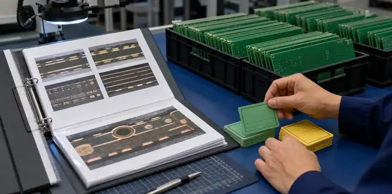
Illustrative specimen and record comparison; not a photograph of this investigation.
Agree which boards and package locations may be destroyed, what evidence the laboratory will retain, and who will receive the resulting material. That agreement should cover the intact assembly, any separated package, fracture photographs and the remaining sectioned pieces. It prevents an investigation from ending with a single image and no specimen that another analyst can examine.
Give each sample a durable identifier linked to the PCB lot, assembly revision and known reflow or rework exposures. Record its panel position when that information exists. Unknown history stays unknown; filling the gap with an assumed normal production route can hide the event under investigation.
If component removal becomes necessary, resolve the evidence plan before following a large-PCB rework procedure. Heating and separation can alter the original condition. Keep enough untouched material for comparison, and agree on the dismantling method with the analyst who will interpret the fracture.
Choose Evidence That Locates the Fracture
Choose the method according to the question: mapping separation across an array, locating the crack through the laminate, or comparing resistance under controlled loading. These outputs complement one another, but they are not interchangeable pass certificates.
| Method | Useful output | Limitation to address |
|---|---|---|
| Dye and pull | Stained interfaces and their distribution across the separated array | Penetration and separation artifacts affect interpretation |
| Targeted microsection | Crack position relative to copper, resin, glass and solder | A limited plane is examined and preparation can disturb the site |
| Pin pull or cold ball pull | Force response and classified failure mode under specified conditions | Coupon and attachment variables differ from a populated assembly |
| Controlled bending with acoustic emission | Fracture events during a defined loading experiment | Events require calibration and physical failure-mode confirmation |
Dye penetration and separation artifacts
IPC-TM-650 2.4.53 describes the dye-and-pull method and preparation considerations. Flux residue can obstruct penetration, while wet dye can smear during separation. Ask the analyst to distinguish stained pre-existing surfaces from fresh separation damage and to describe uncertain indications.
Request an array map tied to component orientation and the photographs. A colored patch without a known land coordinate cannot reliably be compared with the failing net or the load direction. Agree on interpretation with the laboratory and customer; no universal stained-area percentage is proposed here.
Section the suspected fracture path
Select the section from the electrical location, array map and physical observations. Record which row or corner the plane intersects. If the suspected path changes direction or lies outside that plane, further sections may be needed. Preserve the interpretation as local to the sampled region rather than extending it across the entire assembly. Keep the original component orientation on the section map so a second analyst can locate the same region.
Compare Samples Across the Suspect Operation
Use matched specimen groups to investigate when damage appears. Destructive analysis prevents examining the same intact land both before and after an operation. This comparison uses different boards, each analyzed destructively only once. Plan their allocation before the suspect step, rather than selecting only failed boards afterward.
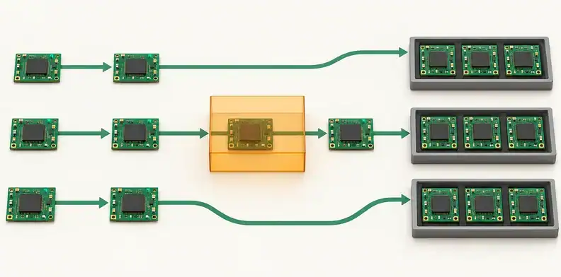
Illustrative sampling routes: baseline before the operation, exposed through it, and retained outside it. Symbols do not specify sample counts or outcomes.
The design below applies two published principles. TM-650 2.4.53 §§4.5 and 5.3–5.5 address stress introduced during sampling and preparation; §§5.6.4.2, 5.10.3 and 5.14–5.15 address penetration, smearing and reporting. NIST’s guidance on blocking explains controlling nuisance variation through comparisons within homogeneous groups. Neither source defines this three-group design. It is an engineering application of those principles, not a complete randomized-block experiment or a claim of QueenEMS test results. Have the laboratory review allocation, sample size and analysis before proceeding.
| Specimen group | Exposure | What the comparison can address |
|---|---|---|
| Baseline | Removed from the route before the suspect operation | Whether comparable assemblies already contain the observed damage |
| Exposed | Passed through the recorded suspect operation | Whether the observed damage population changes after that step |
| Retained comparison | Kept out of that operation; sent for analysis with the exposed group, with storage and handling documented | A comparison for elapsed time, handling and shared analysis preparation |
Match the PCB construction, assembly lot, component configuration and thermal history as closely as practical. Balance corresponding panel positions across groups instead of comparing one panel edge with an unrelated center population. Use the same analytical procedure and record any preparation differences. Blind sample identities during interpretation when practical, so the expected result does not influence classification.
Interpret the groups without overstating causation
Cracks in baseline and exposed groups prevent a simple claim that the operation created every defect. Damage found only after exposure supports investigating that operation, but cohort variation and preparation effects remain possible explanations. A retained specimen with damage also needs interpretation; it does not automatically prove that the laboratory caused it.
Compare location and fracture mode as well as the number of findings. Repeat the comparison after a controlled intervention. Stronger attribution requires a consistent change in the relevant damage under matched conditions, together with evidence explaining the load path.
Connect Pad Strength Tests with Production Strain
Keep susceptibility and exposure as separate measurements. A controlled land test compares a construction under specified loading. A production strain study measures what the real operation applies near the vulnerable package. A favorable result on one side does not establish the other side.
Keep pull-test comparisons on the same basis
Record pad geometry, laminate construction, conditioning, thermal history, attachment, alignment, loading rate and observed failure mode. An attachment failure belongs in a different category from a dielectric crater. Report the valid population and its spread rather than selecting the highest pull force.
The iST/iNEMI cold-ball-pull study cautions against transferring absolute force comparisons across different PCB fabrication contexts without an appropriate basis. A supplier’s number cannot become a product acceptance limit merely because it is larger. The published institutional abstract for Roggeman and colleagues’ joint-level study also distinguishes overload strength from repeated-load behavior; loading conditions can affect the comparison.
IPC-9708 organizes pad-cratering characterization methods. Its public contents identify test variables and reporting, while the official revision table marks the 2010 document as “No Longer Maintained.” Specify the agreed method and revision without inventing a universal pull-force or microstrain threshold.
Universal Instruments’ glass-weave study summary reports that pad position relative to reinforcement affected performance in the construction examined. The work examined a single glass-weave and resin system. Match a comparative coupon to the relevant production construction; the laminate trade name or Tg value alone does not establish the local fracture response. Ask whether the coupon used the same outer-ply construction and copper treatment as the production board, and record differences before interpreting the comparison.
Interpret the two evidence lines together
The iST/iNEMI study states that cold-ball-pull strength cannot guarantee shipping or service reliability. A 2013 Cisco study also describes the difficulty of correlating test methods and translating results into functional-assembly failures. The following decision aid applies those limitations; it is not a model validated by either paper. “Improved” means relative to a documented comparison under comparable conditions, without a universal threshold.
- Only coupon performance improves: production loading remains unresolved. Check the actual operation’s exposure and the associated physical damage.
- Only measured strain decreases: reduced exposure does not establish an undamaged laminate. Check the fracture evidence and required electrical function.
- Both improve: retain the result as comparative evidence, then reverify the released assembly configuration. Two favorable measurements still do not guarantee reliability.
- Both appear favorable but cracks remain: revisit specimen matching, local construction, load direction and rate, measurement placement, and failure classification. A favorable summary value can conceal a different population or mechanism.
Record which situation applies and the next check. Keep pull-force and strain results in their own units; this framework supplies no conversion between them and no release criterion.
Match the Corrective Action to the Confirmed Damage
Select a candidate change from the observed fracture and the measured operation. Avoid simultaneously changing the fixture, laminate and land pattern unless a designed experiment accounts for their combined effects. Otherwise, an improved result may leave the responsible change unknown.
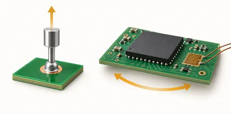
Conceptual illustration of controlled land loading and assembly strain measurement; not a test-setup specification or a conversion between measurements.
| Confirmed finding | Candidate change | Trade-off or prerequisite | Verification |
|---|---|---|---|
| A recorded operation loads a vulnerable region | Revise that operation’s force application or reaction arrangement | Preserve access and the intended electrical test | Repeat exposure measurement and matched physical examination |
| A defined land construction is susceptible | Evaluate a package-compatible land alternative | Routing, mask registration and fatigue behavior can change | Compare constructions under the same conditions, then test the assembly |
| A laminate construction performs poorly in the agreed study | Evaluate a controlled material or construction alternative | Electrical and fabrication requirements still apply | Repeat representative conditioning, characterization and assembly loading |
| Damage correlates with a particular thermal history | Investigate the recorded process or rework exposure | Correlation alone does not establish the mechanism | Hold other variables constant and verify the fracture population again |
Keep land-pattern changes package specific
NXP’s AN5126 describes a thermal-fatigue and drop/shock trade-off between non-solder-mask-defined and solder-mask-defined lands for the packages it discusses. Read that qualification alongside the actual component recommendation. A larger SMD land is a candidate to evaluate, not a universal cure.
Use the existing SMD versus NSMD design comparison for the geometry background. Keep the change bounded to the package and failure being investigated. Confirm the proposed copper and mask geometry with the component and fabrication requirements before testing.
The associated solder-mask opening specification must remain consistent with that proposal. Higher Tg, extra thickness or added underfill likewise needs product-specific support. A change that redistributes stress can shift the failure location, so inspect the new fracture mode as well as the electrical outcome.
Build a Failure Record Another Engineer Can Check
Make the record connect each observation to an identifiable specimen, land and event. “BGA failed after test” leaves open whether the test found damage, introduced it, or merely preceded its discovery.
Include the following information in the investigation package:
- Board identifier, PCB lot, assembly revision and component reference designator.
- Array orientation, ball coordinate, net when known, and the location of each photographed or sectioned site.
- Recorded route through the suspect operation, including tooling revision and any extra diagnostic loading.
- Reflow and rework history, with missing information identified.
- Specimen group, analytical method, preparation conditions and retained material.
- Fracture classification, supporting images, comparison findings and unresolved alternatives.
- Proposed configuration change and the conditions used for its repeat evaluation.
For example, an illustrative entry could describe a dielectric crack beneath a named corner land on a specimen taken after a fixture cycle, while leaving initiation time unresolved. Keep that observation separate from a hypothesis that the fixture initiated the crack. Add the baseline and retained-group findings before changing the hypothesis into a conclusion. This example describes a reporting approach, not an actual factory incident.
Verify the Change on the Released Board Configuration
Recheck the candidate fix on the configuration that production will use. Preserve the comparison method, exposure definition and physical damage classification so the result can be assessed against the original investigation. Record any unavoidable changes in specimens or preparation that weaken that comparison.
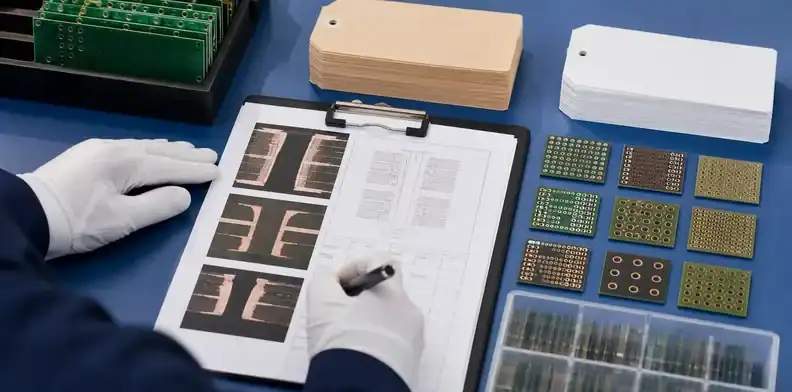
Illustrative review of cross-section records and test coupons; not pad-cratering test results.
Verify both the mechanical outcome and the required electrical function. Even when coupon performance and measured strain both improve, physical examination must address whether the relevant damage changed on the released assembly. A different fracture mode needs its own disposition. An electrically passing board alone does not close a documented laminate-fracture concern.
Before releasing the revised process, agree which changes reopen the assessment. A new board construction, package, hardware arrangement, thermal exposure or fixture revision can alter the assumptions behind the comparison. Retain the accepted setup and its evidence with the released configuration, rather than referring a later production lot to an unidentified successful prototype.
If you are revising or moving a BGA build after a suspected pad-cratering failure, send QueenEMS the project package with the board data, BGA reference and location, assembly sequence, available fracture evidence and the proposed change. State which failure analysis is already complete and which specialist work still needs to be arranged, so the quotation and engineering review address the actual scope.
Written by the QueenEMS Engineering Team
Upload your files today · Free DFM check before production · Ship worldwide
Get your PCB prototypes in as fast as 24 hours. We handle FR4, Rogers, and hybrid boards up to 40 layers in volume production, with advanced builds subject to engineering review — free prototypes for 2–4 layer FR-4 boards, no minimum order.
Just upload your Gerber + BOM — we source every part, assemble, and inspect (AOI + X‑Ray) so you don't have to chase suppliers. Boards ship in as fast as 24 hours.