
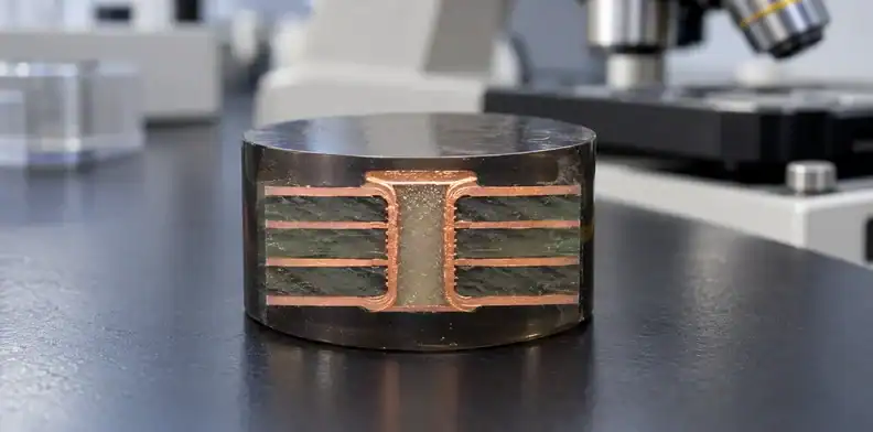
Quick Answer: Copper wrap plating continues from the plated hole wall around the hole shoulder onto the adjacent surface; cap plating covers the filled opening. A cap reading, total surface copper value or flat pad does not, by itself, establish the wrap result. Specify the required copper features separately and request sections that identify the measured deposits; an unresolved boundary needs clarification before a conformity decision.
A copper wrap plating report can look complete while leaving the requested wrap unmeasured. The supplier may have provided a clear cap thickness, a surface copper result and a smooth pad, yet none identifies the copper that extends from the barrel across the hole shoulder.
This comparison starts with a filled-via construction that has already been selected and connects its drawing requirements to identifiable readings.
Table of Contents
- What Copper Wrap Plating Covers on a Filled Hole
- Why Cap, Total Copper and Flatness Cannot Prove Wrap
- Confirm the Via Route Before Choosing Its Evidence
- Write Wrap and Cap as Separate Drawing Requirements
- How One Buyer Requests Separate Wrap and Cap Results
- Worked Review: Cap Reported, Wrap Still Unanswered
- Identify Deposits Before Measuring the Wrap
- Resolve Ambiguous or Inferred Wrap Results
- Keep Reliability Claims Within the Test Evidence
- Review Wrap and Cap Evidence Before Fabrication
What Copper Wrap Plating Covers on a Filled Hole
Wrap is the plated copper extending continuously from the hole wall around its shoulder onto the surrounding surface. The cap is the copper deposited over the filled opening. They occupy different regions of the structure, so a measurement must say which region it represents.
Barrel copper and wrap can be continuous parts of the same deposit. Calling them different inspection targets does not mean that they are different metals or that a sharp boundary must separate them at the shoulder. The boundary that matters when reviewing deposited layers is the one needed to identify the copper included in the requested reading.
The NASA-authored study of copper wrap specifications illustrates the cap, wrap and fill separately. Its definition helps locate the features; its historical IPC references should not supply the acceptance numbers for a new order.
Keep the original foil, later copper deposits and final surface finish identifiable in the drawing discussion. A generic label such as “surface copper” can include different contributions depending on the manufacturing route and measurement location.
The distinction between copper-filled microvias and resin-filled via-in-pad structures remains a separate decision; this review begins after that choice.
Why Cap, Total Copper and Flatness Cannot Prove Wrap
Each observation answers its own question. A cap measurement describes the copper over the fill, while a total surface reading may combine deposits that the wrap requirement needs to distinguish. Surface flatness describes geometry rather than the identity or thickness of an underlying deposit.
Illustrative filled-via inspection scene; the image provides no thickness or conformity result.
| Observation in a report | What it can describe | What remains unanswered about wrap |
|---|---|---|
| Barrel copper reading | Copper at the marked hole-wall location | The required surface extension and its reading |
| Cap thickness | Copper over the filled opening | Which copper belongs to the wrap |
| Total surface copper | Combined copper at the stated location | The separate contributions unless the method resolves them |
| Dimple or crest measurement | Depression or projection of the filled-hole surface | Wrap thickness and continuity |
| Smooth pad photograph | Visible surface condition | The buried deposit interfaces |
Where planarization changes what you can see
In the polymer-filled PTH route discussed in the NASA paper, filling and curing are followed by planarization. Removing excess fill can also remove copper already present around the opening. A later cap then adds copper over the filled region.
The finished surface can therefore answer a cap or geometry question while leaving the remaining wrap unresolved. That is a reason to identify the deposits, not a conclusion that every planarized board has thin wrap or that every thick cap conceals a defect.
Keep ordinary fill voids, cap condition and surface geometry within the separate resin-plug via acceptance discussion.
Confirm the Via Route Before Choosing Its Evidence
Use the actual via construction to decide which deposits must be identified. A resin-filled mechanical PTH, a buried filled connection and a copper-filled laser microvia should not inherit one inspection drawing simply because all are described as filled vias.
Ask the fabricator to relate the drawing to the relevant plating, filling, planarization and subsequent plating operations. The following questions describe information to confirm, rather than universal process sequences.
| Selected construction | Deposits or interfaces to confirm | Evidence question |
|---|---|---|
| Resin-filled and copper-capped PTH | Hole-wall deposit, retained surface wrap and later cap | Can the reported section distinguish the requested wrap from cap? |
| Filled connection subsequently buried | Relevant layer pair and copper present before later lamination | Which section represents the specified finished structure? |
| Copper-filled laser microvia | Actual filled-copper structure and applicable requirement | Does the proposed wrap/cap interpretation apply to this construction? |
The existing HDI rigid-flex manufacturing-stage discussion explains why layer access and manufacturing stages matter. This article adds the narrower question of whether those records identify the wrap and cap quantities being requested.
Write Wrap and Cap as Separate Drawing Requirements
Give each copper requirement its own name and a reference to the approved acceptance document. The drawing and purchase specification should make it possible for the laboratory to report wrap without silently including cap or original foil in that result.
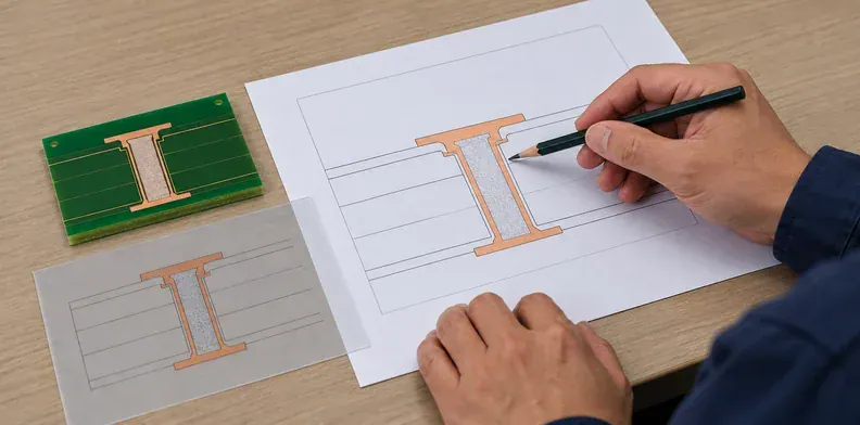
Illustrative drawing-review scene; the approved order documents must contain the actual requirements.
Use the governing document and revision
The IPC-6012F public table of contents lists copper wrap and copper cap plating in separate sections. It also distinguishes filled-hole measurement illustrations. Those headings confirm separate subjects; the public contents do not establish the numerical limit or measurement rule for your board.
Record the specification revision, applicable addendum and drawing requirements used for the order. A remembered value from a paper citing IPC-6012B or C cannot establish compliance with a different requirement. Use the existing IPC Class 2 and Class 3 comparison for the broader classification decision, then confirm the actual clauses governing this structure.
Tie each requirement to its copper feature
Separate the required result from the method used to obtain it. The customer specifies the acceptance need; the fabricator and laboratory must confirm how the chosen structure can be examined and reported.
| Drawing or order field | Purpose | Wording that leaves a gap |
|---|---|---|
| Barrel, wrap and cap requirements | Identify the copper target for each result | “Copper thickness” without a location |
| Governing document and revision | Establish the applicable acceptance basis | An unqualified reference to “IPC” |
| Via construction and layer span | Connect the requirement to the intended hole | One note applied to every filled feature |
| Annotated measurement location | Show which deposit the reading includes | An isolated number with no marked position |
| Required report scope | Agree what must accompany the result | “Standard report supplied” without its contents |
An approved measurement procedure can remain a separate controlled document. Its relationship to the required reading should still be clear before the drawing is released.
How One Buyer Requests Separate Wrap and Cap Results
A real procurement example shows that at least one buyer requests these quantities separately. In its May 2026 tender for third-party PCB coupon microsection analysis, ISRO’s U R Rao Satellite Centre names dimple depth, cap plating thickness, wrap copper thickness and any crest in specified filled-via photograph deliverables.
The relevant entries appear in Annexure-A’s deliverables and example photo report, at PDF pages 12 and 21, printed Annexure pages 9 and 18. The URSC laboratory tender does not impose those four fields on every photograph. Nor does its example acceptance wording establish a universal wrap criterion.
For a fabrication buyer, the useful lesson is the separation of named results within a photograph. Requesting only “a microsection report” leaves the supplier to infer whether a cap result, a combined copper reading or a separately resolved wrap result is expected.
This example concerns a laboratory service, not a board manufacturer’s qualification, and it has no demonstrated connection to QueenEMS. Its field names can inform an order discussion without importing its default values, sample plan or acceptance wording.
Use the broader microsection report requirements for ordinary report completeness. The additional question here is whether the specified wrap and cap are independently identifiable in the supplied evidence.
Worked Review: Cap Reported, Wrap Still Unanswered
Match each requirement to the evidence that actually answers it. Consider this illustrative review: a drawing requires separate wrap and cap results, but the supplied report contains a marked cap reading, a total surface copper reading and a statement that the pad is flat. No numerical measurements or actual production results are assumed in this example.
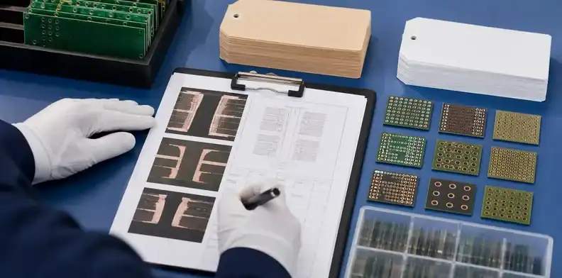
Illustrative report-review scene; the example below contains no measured production data.
| Requirement being reviewed | Evidence supplied in this example | Review outcome |
|---|---|---|
| Cap thickness | A value at a marked cap location | The cap question can be reviewed against its specified requirement |
| Wrap thickness | No separately identified reading | The wrap question remains unanswered |
| Wrap continuity | A smooth top-surface photograph | The photograph does not establish the requested cross-sectional feature |
| Total surface copper | A combined reading at a stated location | Useful for its own requirement; not automatically a separate wrap result |
| Surface geometry | A flatness statement | Review separately from copper-layer identity |
The supplied results may be valid within their stated scope. The error would be approving the wrap requirement because a different feature has been measured. Equally, the absent wrap result does not establish that the physical wrap is defective.
Ask for the missing wrap result
A focused clarification could read: “Please identify the wrap deposit and its measurement location on the section, report it separately from cap, and state the method or limitation where the boundary cannot be distinguished.” This asks for the missing information without disputing an otherwise usable cap measurement.
QueenEMS’s published QC report sample contains a general PTH measurement record. It should not be treated as proof that a particular filled-via wrap/cap requirement has been measured. Check the sample report against the proposed order’s features before agreeing the delivery scope.
Identify Deposits Before Measuring the Wrap
The laboratory must identify the copper included in the wrap result. A sharp-looking image alone does not establish that the marked thickness excludes other deposits. The preparation, visible interfaces and chosen measurement location need to support that interpretation.
When the deposit boundary is visible
In Section II of the NASA author manuscript, the researchers etched microsections to distinguish copper layers before measuring wrap; they excluded cap plating from that measurement. This is a documented example of resolving the target deposit rather than calling the entire surface stack wrap.
For an order report, ask for an image on which the relevant interfaces and reading locations can be understood. The report should identify what each measurement includes and preserve the relationship between the image and its named result. A higher magnification or extra decimal places cannot compensate for an unidentified deposit.
When the deposit boundary remains unclear
Ask the laboratory to describe the limitation instead of labeling an unresolved combined reading as wrap. Clarification may involve suitable re-preparation, another representative section or a documented method appropriate to the route. The method and acceptance decision belong with the responsible laboratory and engineering personnel.
Neither the paper nor this article provides a universal preparation recipe. Etchant, preparation conditions, section selection and acceptance interpretation must suit the actual structure and governing procedure. Preserve the distinction between an explanatory method example and an approved production inspection method.
Resolve Ambiguous or Inferred Wrap Results
Record an unresolved wrap result as an evidence gap and decide how to close it. Keep directly measured values, inferred values and process-stage records distinguishable. Their usefulness depends on the method, the construction and what the order permits.

Illustrative microscopy setup; it does not demonstrate that a particular deposit boundary can be resolved.
| Evidence situation | Can it answer the wrap requirement as supplied? | Clarification to request |
|---|---|---|
| Relevant deposit identified with marked readings | Potentially, subject to the specified method and limit | Confirm the result applies to the required feature |
| Combined surface reading with no resolved interfaces | It does not independently identify wrap | Request layer identification or an agreed suitable method |
| Wrap value inferred from other readings | Only where the documented method is validated and permitted | Obtain the method, assumptions and approval basis |
| Record taken before a later material-removal operation | It describes that earlier stage | Establish how the required finished condition is demonstrated |
| Boundary recorded as not determinable | No thickness conclusion from that record alone | Agree further examination or engineering disposition |
Subtracting one reported thickness from another is not automatically a valid wrap measurement. Different positions, copper contributions or preparation conditions can invalidate the comparison. A method explicitly validated for the construction and permitted by the order requires its own review; this article neither approves nor rules out every differential method.
Earlier-stage records may explain how deposits were formed. They must not quietly replace evidence of a finished condition that the contract specifically requires. Obtain engineering approval for any remaining deviation before release.
For an unresolved drawing-to-report mismatch, request an engineering assessment with the filled-hole detail and the disputed readings. The first task is to confirm what can be established for that route, including any additional inspection needed.
Keep Reliability Claims Within the Test Evidence
A thickness result alone does not predict the service life of a filled-via board. It answers a dimensional question under a stated method. Reliability claims require evidence relevant to the construction and its loading conditions.
NASA’s 2016 copper-wrap investigation reported barrel-centered failure observations under its test conditions. Its modeling assumed good, defect-free construction, and the study explicitly left severely mismatched fill-material expansion outside its scope. Those limits prevent a universal conclusion that increasing wrap thickness always extends board life, or that omitting wrap is generally safe.
Material and fill behavior remain relevant to a particular structure; the separate PCB Z-axis CTE discussion addresses that selection problem. A wrap report should not replace it with a single thickness-to-reliability claim.
Research findings also do not waive an order requirement. Establish dimensional conformity against the governing document, and evaluate any additional reliability qualification on its own evidence and scope.
Review Wrap and Cap Evidence Before Fabrication
Before releasing the job, settle which copper features are required and how each result will be demonstrated. Any open question should name the feature, the missing information and the person responsible for approving its disposition.
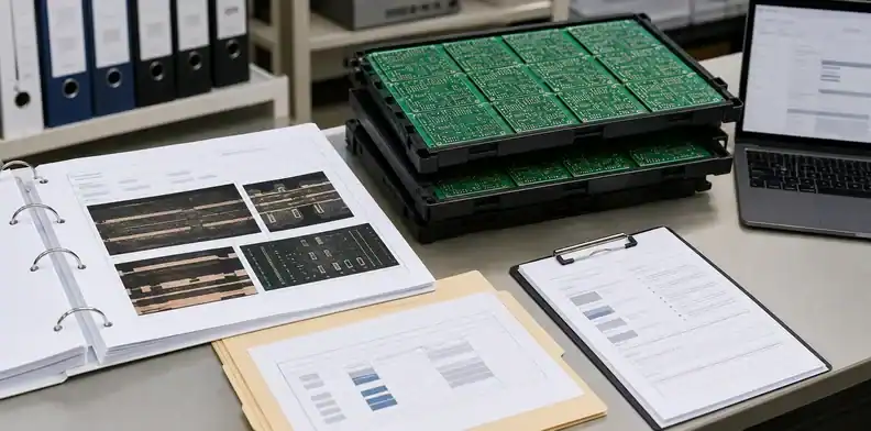
Illustrative fabrication-review package; it contains no approved customer drawing or actual acceptance result.
QueenEMS lists filled and capped via-in-pad among its PCB manufacturing services. That service description establishes relevance to the inquiry; the specific construction and inspection deliverables still need engineering confirmation.
Review the filled-via drawing and proposed report together:
- Confirm the selected hole construction and relevant layer span.
- Identify the separate barrel, wrap and cap requirements in the order documents.
- Agree how the report will distinguish the copper included in each reading.
- State what happens when the final section does not resolve a required boundary.
- Confirm which inspection and report deliverables the fabrication quote includes.
The service name “filled and capped” does not close these questions. A supplier may offer that construction while needing further review of a particular wrap requirement or reporting method. Resolve the difference before treating an inspection package as an agreed deliverable.
For a PCB fabrication quotation, send QueenEMS the filled-hole cross-sectional detail, stackup, via list by construction, governing specification and revision, and the separate wrap/cap reporting requirements. Include an example report when it illustrates the unresolved measurement. Request confirmation of the manufacturing route and inspection scope before accepting the quote; specialist layer measurement remains subject to that engineering confirmation.
FAQ
Is edge plating the same as filled-hole wrap plating?
No. Edge plating concerns metallization along a board edge. Filled-hole wrap concerns the plated deposit continuing from a hole wall around its shoulder onto the adjacent surface. Clarify which feature a supplier means when it uses “wrap” in a capability list.
Is the surface finish part of the copper cap?
No. Report the specified surface finish separately from the copper cap. A finish measurement does not establish cap thickness, and a cap reading does not establish the thickness or condition of that finish.
Does a Type VII designation prove that wrap conforms?
No. A filled-and-capped treatment designation does not demonstrate the separately required wrap result. Confirm the applicable acceptance document and the evidence for the actual structure rather than using the treatment name as a conformity statement.
Is a board rejected if the wrap boundary cannot be identified?
Not automatically. An unresolved boundary may leave insufficient evidence to judge the wrap requirement. Obtain suitable clarification and follow the order’s agreed disposition process; do not turn a missing measurement into an unsupported physical pass or fail.
Do copper-filled microvias use the same wrap and cap check?
Confirm the requirements for that construction. Do not transfer a resin-filled PTH interpretation to a copper-filled laser microvia without checking its deposited structure, applicable specification and approved examination method.
Written by the QueenEMS Engineering Team
Upload your files today · Free DFM check before production · Ship worldwide
Get your PCB prototypes in as fast as 24 hours. We handle FR4, Rogers, and hybrid boards up to 40 layers in volume production, with advanced builds subject to engineering review — free prototypes for 2–4 layer FR-4 boards, no minimum order.
Just upload your Gerber + BOM — we source every part, assemble, and inspect (AOI + X‑Ray) so you don't have to chase suppliers. Boards ship in as fast as 24 hours.