
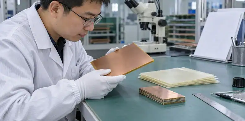
Quick Answer: Arlon 85N is a pure polyimide laminate and prepreg system, but an 85N material name alone does not define a multilayer PCB. Agree the core and bonding-ply construction, thermal exposure, hole geometry, and first-build inspection scope before fabrication. Use the current material and processing documents to review the proposed build; typical material properties do not qualify every finished board.
An Arlon 85N PCB quotation needs a construction that both the designer and fabricator can identify. A drawing that says only “85N, high temperature” leaves the bonding plies, pressed dielectric spacing, and processing assumptions open. Those omissions become harder to resolve after copper patterns, drill tools, and purchasing commitments have been fixed.
Table of Contents
- Lock the Arlon 85N grade and document revision
- Turn thermal properties into a board requirement
- Define the core and prepreg build by layer
- Keep moisture controls tied to the processing stage
- Check inner-layer treatment and rinsing together
- Approve product heating before accepting the press cycle
- Match hole preparation evidence to the actual geometry
- Carry the 85N process review through finishing and routing
- Review substitutions and loss requirements separately
- Submit an 85N fabrication package with a defined first build
Lock the Arlon 85N grade and document revision
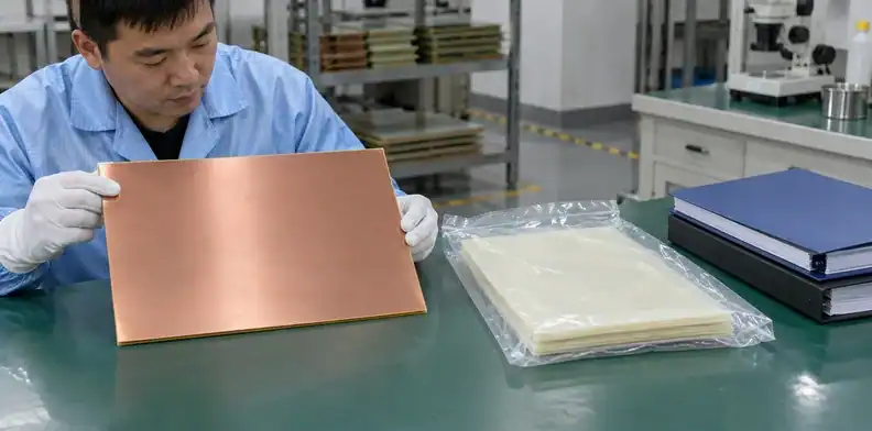
Specify Arlon 85N by manufacturer, exact grade, and the agreed technical-document revision. Identify the laminate cores and prepreg bonding plies separately so that a material certificate can be checked against the actual layer schedule.
Arlon describes 85N as pure polyimide with no epoxy added, blended, or reacted. Its 85N datasheet v1.7 lists the material against IPC-4101/40 and /41. That description helps identify the resin system; it does not specify every thickness, reinforcement construction, copper foil, or finished-board acceptance requirement.
| Item to identify | What belongs in the 85N order | What the document can establish |
|---|---|---|
| Material designation | Manufacturer and exact 85N grade | Which material system is proposed |
| Technical basis | Agreed datasheet and processing-guide revisions | Which property conditions and recommendations were reviewed |
| Core construction | Laminate designation, dielectric thickness, and copper construction | Which cured sheets form the multilayer |
| Bonding construction | Prepreg designation and ply count by layer gap | Which bonding materials the press book uses |
| Supply record | Material lot identification linked to the build | Which supply record accompanies the proposed construction |
Check all five items together. A certificate bearing the right family name cannot resolve a bonding-ply change that never appeared in the approved stackup.
Older 85N documents remain available online, including distributor copies with different property and process tables. Date and revision belong beside any figure used in a design review. When another high-temperature grade is proposed, the VT-901 material specification discussion shows why the review must follow that specific grade’s documents; a generic “polyimide equivalent” note is too broad to authorize a change.
Turn thermal properties into a board requirement
Use the 85N thermal figures to select a material candidate, then state the board’s actual service temperature and assembly exposure. A high glass transition temperature does not supply a continuous operating-temperature rating or a finished-board life prediction.
The current datasheet reports a typical glass transition temperature, or Tg, of at least 250°C by thermomechanical analysis. It also reports 1.2% Z-axis expansion over 50–260°C. Keep that measurement interval attached to the expansion value; it cannot be applied unchanged to a different temperature range or converted directly into a plated-hole fatigue life.
| Material information | Scope shown by the 85N sheet | Requirement still needed for the PCB |
|---|---|---|
| Tg of at least 250°C | Typical material result by the stated test method | Temperature, time, and mechanical/electrical demands in service |
| Z expansion of 1.2% | Measurement over 50–260°C | Actual construction and thermal exposures used for hole evaluation |
| Compatibility with lead-free processing | Material application statement | Intended assembly profile and number of hot excursions |
| UL-94 HB classification | Material flammability entry | The product’s specified flammability and certification requirements |
Compare these requirements before accepting the material. The HB entry should not be rewritten as V-0, and a laminate classification should not be presented as certification of the completed PCB.
An equipment board held hot for long periods and a board exposed briefly during soldering have different thermal histories. State the relevant duration, peak conditions, repeated assembly or repair exposures, and any required qualification procedure. The fabricator can then assess the proposed 85N construction against an identifiable application instead of an undefined “high-temperature” claim.
For a project still choosing its resin family, resolve the BT and polyimide application trade-offs first. Once 85N is selected, the remaining work is construction and verification.
Define the core and prepreg build by layer
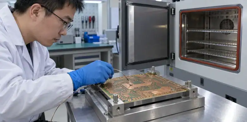
Define cured cores, bonding plies, and required post-press dielectric gaps in the layer schedule. Total board thickness alone cannot establish the spacing around each signal layer or the resin needed to encapsulate its copper pattern.
Ply identity and pressed spacing are different fields
A core is already cured; prepreg contains the resin that flows and cures while joining the multilayer. The 85N sheet lists several prepreg glass styles and resin contents, along with scaled-flow characterization. Those entries help identify the supplied ply, but they are not a guarantee of its thickness at every location in your pressed board.
| Construction field | Specify for the 85N build | Review with the fabricator |
|---|---|---|
| Cured core | Grade, dielectric thickness, copper on each face | Proposed available core construction |
| Bonding plies | Exact prepreg designation and number of plies | Resin and reinforcement suitable for the adjoining copper |
| Copper relief | Starting copper and patterned regions | Areas requiring resin fill during pressing |
| Finished dielectric gap | Controlled layer pair and permitted spacing | Expected pressed spacing and how critical locations will be checked |
Keep the supplied-ply designation and finished-gap requirement in separate columns. Changes to either can affect the other, so they should be reviewed together.
Review copper relief before changing the bonding plies
Consider an illustrative layout with a dense copper region beside a broad cleared window. Resin must fill the etched relief while enough dielectric remains over the copper. Replacing a bonding ply to reach the same nominal board thickness can change the available resin and the local spacing; matching total thickness does not settle that question.
Have the construction proposal identify the two regions and the intended cross-section locations. A first-build section can then be compared with the relevant layer gap and copper pattern. This example proposes a check, not a measured result or a universal minimum ply count.
Also separate core thickness, bonding thickness, and finished copper when reviewing overall PCB thickness and mechanical fit. That prevents a connector-fit dimension from being mistaken for the controlled dielectric spacing in the 85N stack.
Keep moisture controls tied to the processing stage
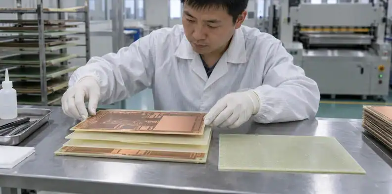
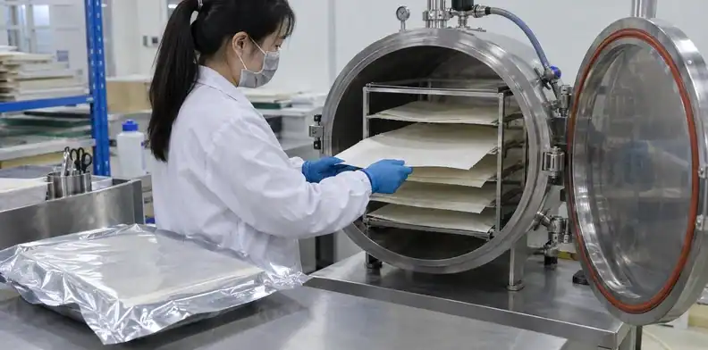
Treat prepreg drying before layup and finished-board baking before a later thermal excursion as separate controls. A record of the second operation does not establish that moisture was controlled when the original interlayer bond formed.
Arlon’s 85N Processing Guide v1.1a discusses controlled prepreg storage, equilibration before use, vacuum drying, and additional precautions before subsequent heat. It explains that retained moisture can affect resin flow and inner-layer bonding. Its recommendations apply to named processing stages; they should not be collapsed into a single bake instruction attached to every shipment.
For example, a supplier response might document a bake immediately before hot finishing while leaving the prepreg’s bag-opening and layup history unanswered. Ask for the earlier handling information before interpreting the bake as a complete moisture-control response. Suspect prepreg needs a material and process assessment before it is pressed into a board.
A useful sequence identifies the material lot, storage conditions, when it was removed from controlled storage, equilibration, drying, and the interval before layup. These are proposed review fields, not a claim about QueenEMS equipment or a mandatory reporting format from a standard.
Use the supplier’s applicable material guidance and documented process to determine times and conditions. Board thickness, humidity exposure, and the next hot operation can change the finished-board handling plan. Extending an arbitrary bake cannot demonstrate the quality of a bond already made.
Check inner-layer treatment and rinsing together
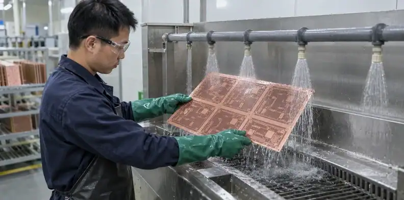
Review copper surface treatment and removal of process residues as a combined bonding step. An oxide-treatment name or a dark surface color alone does not establish that an 85N inner layer is ready for lamination.
The original 85N processing guide discusses brown oxide or suitable oxide alternatives and explains the risks from retained alkali after treatment. It also cautions against older black-oxide chemistry for this application. The review therefore needs both the proposed treatment’s compatibility and the subsequent cleaning and rinsing conditions.
A bond problem can involve surface preparation, residual chemistry, moisture, resin flow, or thermal processing. Treating all of these as “bad polyimide” would skip the observations needed to distinguish them. Preserve the material lot and process sequence, then compare the affected interface with the construction and preparation used for the trial.
The guide also describes bond-quality behavior that does not track a preference for a uniformly dark oxide. An appearance photograph is useful for locating discoloration or nonuniform areas, but it cannot replace a relevant adhesion or laminate observation. Ask what the photograph represents and which further examination supports the supplier’s explanation.
Purchasing can record the proposed treatment and any deviation from the agreed processing basis. The fabricator selects and controls the detailed chemistry; engineering and quality decide whether the resulting observations support the intended build. Copying bath temperatures or dwell times from an online article would leave those responsibilities unresolved.
Approve product heating before accepting the press cycle
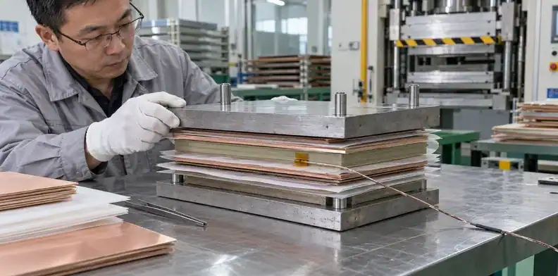
Evaluate the lamination cycle against product heating and the proposed press book. A copied press setpoint does not show when the 85N material reaches the temperature used to start the cure interval.
Cure time must refer to the material in the press book
The v1.7 datasheet gives a recommended cure setting of 218°C and starts its stated 120-minute cure interval when product temperature exceeds 213°C. These are manufacturer recommendations for process development, not universal instructions that approve every press and panel construction.
The processing guide explains that equipment, panel size, book loading, thickness, and copper affect the suitable cycle. It also states that there is no single correct lamination pressure. Quoting a pressure without its construction and loading context can therefore conceal the resin-flow question that the pressure is supposed to address.
Ask how the product-temperature basis was established, which part of the proposed book it represents, and how the supplier relates that basis to its control settings. The response should connect the actual buildup and process assessment to the proposed temperature-and-time settings.
An illustrative review of a thick 85N press book
Suppose a proposed build contains thick cores and substantial internal copper. The quotation response lists the press temperature and cycle duration, but it provides no explanation of product heating. That response leaves the material’s time at the relevant temperature unresolved, even though the machine setting resembles the datasheet.
A proposed follow-up is a documented trial using a representative book and identified product-temperature measurement locations. Review the resulting temperature traces, the supplier’s cure-time interpretation, and the local laminate sections selected for the construction. The fabricator should explain how those measurements represent the slower-heating or otherwise critical parts of its book.
This is an illustrative engineering review, not a report of a successful QueenEMS trial. Sections and electrical continuity can contribute evidence about the fabricated sample; neither alone demonstrates its lifetime under the application’s thermal history. The trial plan should state which construction and processing questions it resolves before the same cycle is accepted for repeat production.
Match hole preparation evidence to the actual geometry
Identify the production hole groups and examine preparation before relying on plated sections. A coupon with a thinner construction or easier hole geometry cannot automatically establish the condition of the narrowest, deepest holes in the 85N board.
The original guide recommends assessing hole-wall quality before and after desmear or etchback and identifies plasma and alkaline-permanganate approaches for polyimide. The method still needs settings and an assessment suited to the actual construction. Merely naming “plasma” does not establish that resin was removed adequately or that the subsequent interconnection is sound.
| 85N feature group | Observation to relate to the build | Limitation to resolve |
|---|---|---|
| Thick-board plated through holes | Hole geometry and preparation through the relevant depth | A shallow trial hole may not represent the production group |
| Inner-layer connections | Resin removal and the condition at captured copper layers | A section between connections can miss the relevant interface |
| Narrow finished holes | Plated wall geometry at agreed inspection locations | One favorable section is not a distribution across the lot |
| Critical hole coupon | Stack, processing history, and hole group represented | Coupon evidence needs a stated relationship to production boards |
Select the hole groups before arranging the trial and report. The table identifies representation questions; it does not prescribe a universal plating thickness, sample count, or acceptance class.
For the resulting documentation, use the cross-section report fields and measurement review to check magnification, locations, dimensions, and specimen identity. Keep the 85N construction and relevant thermal treatment attached to the sample record so engineering can tell what the section actually supports.

Carry the 85N process review through finishing and routing
Include finishing heat, solder-mask condition, and routed-edge quality in the 85N build review. Laminate selection leaves these finished interfaces to be specified for the assembly and mechanical application.
Arlon’s processing guide discusses compatible finishing and mask processes, handling before hot operations, and monitoring router wear and edge quality. That guidance is a starting point for the fabricator’s proposed route. It does not guarantee that a particular finish, mask material, or cutting setup meets your product requirement.
State the finish and the assembly interfaces it serves, including any contact area with a separate coating requirement. Identify later heat exposure in the process proposal. Where solder-mask bonding or cure is a release criterion, the mask adhesion and cure acceptance discussion belongs alongside the chosen mask and the agreed specimen or inspection scope.
For profiling, identify the edges that affect connector access, enclosure fit, or a nearby copper feature. Examine any cracking, fractured material, or burr at those locations as a physical condition, with the drawing and tool history available. A moisture-handling record cannot establish that a mechanically damaged edge is acceptable.
Use the routed PCB edge inspection criteria for the detailed defect and fit questions. The 85N-specific task is to carry the agreed material construction and processing history through to those finished-board observations.

Review substitutions and loss requirements separately
Approve substitute construction and electrical performance separately from the 85N thermal designation. A shared resin family or similar headline Tg does not establish an interchangeable bonding ply or a suitable high-frequency channel.
A similar resin name does not fix the reinforcement
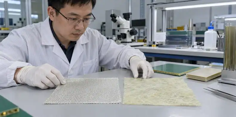
The original 85NT processing guide describes polyimide on nonwoven aramid reinforcement and distinguishes its flow behavior from E-glass constructions. That gives a concrete reason to review an 85NT proposal as a construction change, even where the supplier describes the resin as related to 85N.
Request the exact substituted layer, reinforcement, material designation, and resulting pressed geometry. Retain the original proposal until the changed construction has been assessed. The material substitution approval workflow covers the broader documentation; here, engineering must specifically resolve the 85N core or bonding-ply change.
Frequency-specific loss needs its own evidence
The 85N v1.7 property table lists dissipation factor at 1 MHz and leaves its 1 GHz dissipation-factor entry as N/A. A missing entry supplies no loss value for a GHz channel. Material suitability for a thermal requirement therefore does not settle a separate insertion-loss requirement.
Identify the operating frequency range, routed layer, construction, and electrical evidence required by the design. For a loss-sensitive backplane, use the existing impedance and insertion-loss evidence requirements to define the relevant coupon and channel assumptions. An alternative low-loss layer would need its own material and bonding review; it should not appear as an undocumented change to the 85N stack.
Submit an 85N fabrication package with a defined first build
Send the 85N layer schedule with process-sensitive geometry and a defined first-build inspection scope. That lets the quotation address material procurement, fabrication development, and repeat-lot requirements as identifiable items.
| Package item | 85N-specific information | Question the quotation should resolve |
|---|---|---|
| Material and layer schedule | Exact grade, core construction, bonding-ply designation and count | Can the specified materials support the proposed build? |
| Copper and drill files | Copper relief, thick planes, hole groups, and connection layers | Which geometry needs fabrication assessment or a trial? |
| Thermal requirements | Service exposure, assembly heat, and planned repair excursions | Which processing and qualification scope is being quoted? |
| First-build specimens | Proposed local laminate sections and representative hole groups | What will demonstrate the agreed construction? |
| Repeat-order controls | Approved material build, supply traceability, and change conditions | Which changes require renewed review? |
The first build may include construction development and inspection that a routine repeat order does not. Ask for those activities to be identified in the proposal. Avoid comparing one price that includes a representative trial with another that assumes an already accepted build; neither price is interpretable until that difference is resolved.
A quotation can also remain conditional on the specified core or prepreg being available. Require the proposed supply construction to be named before treating a delivery date as fixed. If a replacement ply changes the local dielectric gap or the resin-fill assessment, engineering needs to review the new layer schedule before purchasing accepts the revised offer.
Send the exact 85N core/prepreg schedule, copper-relief artwork, critical hole groups, and thermal-exposure requirements through QueenEMS’s project quotation contact. Include the proposed first-build sections and tests so the material availability, construction questions, and fabrication quotation can be reviewed together.
Sources
Written by the QueenEMS Engineering Team
Upload your files today · Free DFM check before production · Ship worldwide
Get your PCB prototypes in as fast as 24 hours. We handle FR4, Rogers, and hybrid boards up to 40 layers in volume production, with advanced builds subject to engineering review — free prototypes for 2–4 layer FR-4 boards, no minimum order.
Just upload your Gerber + BOM — we source every part, assemble, and inspect (AOI + X‑Ray) so you don't have to chase suppliers. Boards ship in as fast as 24 hours.