
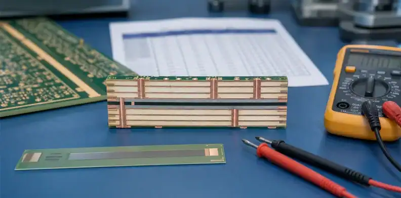
Quick Answer: A buried resistor PCB should not enter quotation until the resistor material, target sheet resistance, tolerance, trim or no-trim approach, layer position, land pattern, test method, and approval owner are clear. The PCB fabricator can build the approved embedded-resistor layer, but the design owner must decide whether the resistor value, tolerance, power, and drift assumptions fit the circuit. For RFQ, send the stack-up, resistor geometry, material callout, value table, measurement points, and any coupon or first-article evidence you expect.
Buried resistor PCB designs reduce discrete parts and free surface area, but they also move a circuit function into the fabrication process. That change affects sourcing because the resistor is no longer a component that purchasing can swap after layout release. It becomes part of the laminate stack, copper pattern, etching process, and final inspection plan.
This article is written for buyers and engineers preparing a manufacturing package. It is not a resistor-network design tutorial and does not replace material supplier design rules, circuit simulation, or reliability qualification.
Table of Contents
- What does a buried resistor change in the RFQ?
- Which resistor data belongs in the drawing?
- How should tolerance and trimming be handled?
- What does layer position change?
- Which tests prove the resistor layer was built correctly?
- Where can CAM review create a hold?
- How should buyers compare quotes?
- What should QueenEMS receive for review?
What does a buried resistor change in the RFQ?
A buried resistor changes the RFQ because a passive electrical value becomes part of the PCB fabrication stack. The supplier is no longer quoting only copper lines, holes, solder mask, and finish. They are also quoting a controlled resistive material, geometry, tolerance plan, and measurement method.
In a normal assembly, a resistor value can often be changed by BOM revision. In a buried resistor PCB, a value change may require layout geometry changes, material changes, stack-up changes, or a new fabrication release. That makes revision control more important than it is for ordinary routing.
The buyer should also separate design ownership from fabrication ownership. The fabricator can say whether the selected resistor layer and geometry are manufacturable. Engineering must approve the value, tolerance, power, temperature behavior, and whether the circuit can accept process variation.
This separation matters during purchasing because an embedded value is not corrected by changing a reel on the SMT line. If the first prototype shows a value shift, the corrective action may be a different resistor body geometry, another sheet-resistance option, or a changed tolerance target. Those are engineering changes with quote and schedule impact, not ordinary buyer substitutions.
RFQ signal: A buried resistor quote is not complete until the electrical value table and the manufacturing acceptance method are both visible.
Which resistor data belongs in the drawing?
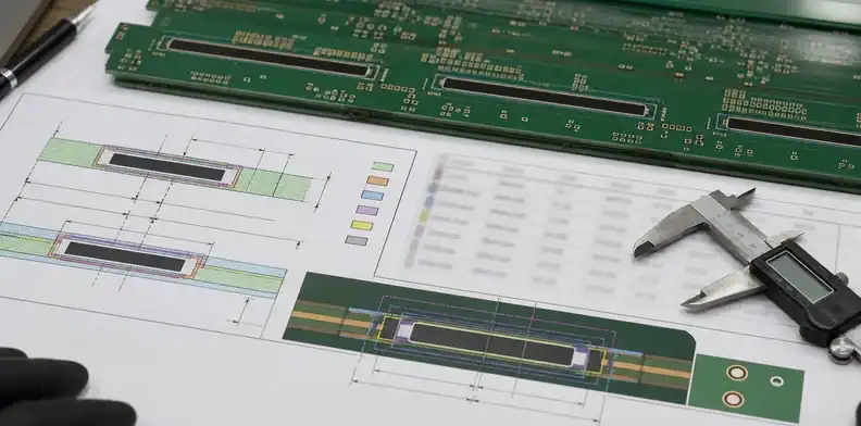
The drawing should state the embedded resistor material, nominal values, acceptable tolerance, layer position, resistor geometry, measurement pads or coupon, and whether laser trimming is required or forbidden. Gerbers alone rarely show the intent clearly enough for procurement.
Use a small value table rather than scattered notes. The table should identify each resistor by reference or net, nominal ohms, tolerance, layer, geometry reference, and test expectation.
| Drawing field | Why it matters | Buyer check before RFQ |
|---|---|---|
| Resistor material | Defines sheet resistance range | Match the material to approved stack-up |
| Nominal value | Sets the circuit target | Confirm value table matches schematic |
| Tolerance | Drives process and test cost | Decide whether trim is required |
| Geometry | Converts sheet resistance into value | Lock length, width, and terminal shape |
| Layer position | Affects processing and access | Confirm the resistor layer in stack-up |
| Measurement point | Makes acceptance possible | Define coupon or accessible pads |
This is also where document precedence matters. When the schematic says one value, the fabrication drawing says another, and the Gerber geometry implies a third, the supplier cannot know which document owns the decision. QueenEMS’ PCB purchase order review article is useful when teams need the PO attachment list to match the released fabrication package.
For repeat orders, keep the resistor table tied to the board revision. A small drawing update that changes an embedded resistor value should not share the same released package name as the previous lot. The purchasing record should show which resistor revision was quoted, approved, and ordered.
Add the approved value table to the PO attachment list when the buyer issues a repeat order.
Release rule: The resistor table should be controlled like a BOM field, even though the feature is built inside the bare board.
How should tolerance and trimming be handled?
Tolerance and trimming should be agreed before quotation because they change cost, schedule, and inspection evidence. A loose embedded-resistor value may be verified by coupon or sample measurement; a tight value can require trim allowance, extra process control, or a different design approach.
The key question is whether the circuit needs the embedded resistor to land inside a tight final value or only within a functional range. Current sense, bias, termination, damping, and pull networks do not all carry the same tolerance risk. The RFQ should not hide that difference.
| Tolerance choice | Manufacturing implication | RFQ action |
|---|---|---|
| Broad tolerance | Lower process burden | State the acceptance range clearly |
| Tight tolerance without trim | Higher geometry and process risk | Ask for capability evidence first |
| Laser-trimmed value | Adds process step and evidence need | Define trim pads, value, and report |
| Prototype-only value study | Not yet production-ready | Mark the job as engineering review |
Avoid asking the board supplier to “meet schematic values” without a method. The supplier needs to know whether measurement occurs on a coupon, an exposed pad pair, a test structure, or the assembled circuit. Each option answers a different question.
Power rating should also be handled before RFQ. The supplier may know the material and process, but the design owner must decide whether the embedded resistor can carry the expected dissipation in the final product. When heat is meaningful, include the assumed current, duty condition, copper spreading area, or a note that the board is prototype-only until thermal validation is complete.
Test rule: Do not buy buried resistor boards on nominal value alone; approve the value, tolerance, measurement location, and trim policy together.
What does layer position change?
Layer position changes manufacturability, repair access, inspection, and sometimes circuit behavior. A resistor on an internal layer may be protected, but it is also harder to inspect directly after lamination. A resistor material near copper planes, heat sources, or high-current areas can create additional design checks.
For a simple buried resistor PCB, the stack-up should identify the resistive layer by name and show what copper layers sit above and below it. For higher-density designs, the release package should also show whether vias, planes, or copper pours are allowed near the resistor body.
The layer decision also affects process sequencing. Some embedded-resistor materials are laminated and patterned in ways that differ from ordinary copper layers. That means a last-minute layer swap can invalidate the quote or trigger a CAM hold.
Connect the embedded resistor decision to the full board construction. If the same board also has controlled impedance, HDI vias, or unusual thickness targets, those constraints need one stack-up owner. QueenEMS can review the broader stack-up decision through its supplier stack-up signoff workflow.
Assembly access is another reason to freeze the layer. Once the resistor is buried, a field or production repair cannot replace it. If the value is used in a calibration path, engineering should decide whether the board needs external trim points, firmware calibration, or a surface component fallback before the fabrication files are released.
Design boundary: The supplier can flag process limits, but engineering owns the resistor layer’s electrical position and nearby-copper rules.

Which tests prove the resistor layer was built correctly?
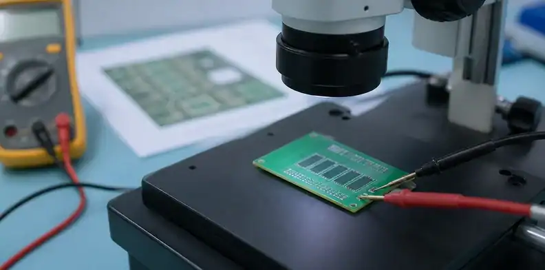
Useful tests prove that the embedded resistor process produced the agreed value or range at the agreed measurement point. The most common evidence is a coupon measurement, first-article value report, or resistance measurement across defined pads. Continuity alone is not enough.
The acceptance method should match the risk. A non-critical bias resistor may only need sample evidence. A resistor used for calibration, current sense, or signal termination may need tighter measurement records and a clear nonconformance response.
| Evidence | What it proves | What it does not prove |
|---|---|---|
| Coupon resistance | Process output near the lot | Exact value of every hidden resistor |
| Pad-to-pad measurement | Accessible feature value | Long-term drift or thermal behavior |
| First-article report | Initial build matches release | Future lots without continued control |
| Microsection support | Layer construction evidence | Electrical performance by itself |
| Assembly test | Product-level function | Bare-board process root cause |
For receiving teams, the most useful package is short and specific. Ask for the value table, measurement method, sample size, and pass/fail rule instead of a generic quality document bundle.
A practical receiving plan can be simple: verify the supplier report against the released value table, check that the coupon or pad names match the drawing, and escalate only values outside the agreed range. That avoids a dispute where purchasing asks for “all resistor data” but the supplier only measured a process coupon.
Acceptance rule: Match the test to the resistor’s job; a calibration path needs stronger evidence than a low-risk pull network.
Where can CAM review create a hold?
CAM review can create a hold when the resistor geometry, material, layer, or measurement method is unclear. Holds also appear when the fabricator sees terminals that are too small, resistor bodies that are too close to copper features, or value targets that do not match the geometry.
These holds should be resolved before the production release, not during final inspection. A buyer who treats CAM questions as paperwork may approve a change that alters resistance or invalidates engineering data.
The most dangerous hold is a proposed geometry cleanup that looks harmless. Rounding a corner, changing a terminal overlap, widening a body, or moving a nearby via can shift value or current density. The CAM response should quote the exact proposed edit so engineering can compare it with the released calculation.
| CAM hold | Practical cause | Safe response |
|---|---|---|
| Material not specified | Resistor layer is visible but unnamed | Provide approved material and sheet value |
| Geometry conflict | Width or length cannot be held | Engineering reviews the proposed edit |
| Value mismatch | Table and layout disagree | Freeze one controlled value table |
| No test access | Hidden feature lacks coupon or pads | Add coupon or define no-test decision |
| Layer swap requested | Stack-up build is difficult | Recheck electrical and process impact |
For jobs with many RFQ questions, use a single response log. QueenEMS’ article on PCB CAM questions before production explains how to keep manufacturing edits from becoming undocumented design changes.
CAM hold rule: Pause when a CAM edit touches resistor length, width, terminal shape, layer, material, or test access.
How should buyers compare quotes?
Compare buried resistor PCB quotes by capability, evidence, and approval flow before comparing unit price. A lower price is not useful if the quote assumes a different resistor material, no trimming, no measurement record, or a tolerance the circuit cannot accept.
Ask each supplier to state the resistor material, expected tolerance, whether trim is included, test method, coupon plan, and what changes would trigger a revised quote. Make those assumptions visible before procurement selects the winner.
Quote comparison also needs schedule realism. Embedded-resistor materials may not follow the same lead time as standard FR4 builds, especially for prototypes or small lots. If the project schedule is tight, ask whether material is stocked, ordered per job, or subject to confirmation after DFM.
Commercial terms should mirror the design risk. If the supplier has to buy a special resistive material or perform extra trimming, cancellation and revision liability may start earlier than for a commodity two-layer board. Procurement should record whether the quote assumes prototype learning, engineering samples, or repeat production.
| Quote line | Safer wording |
|---|---|
| Embedded resistor included | Names material, layer, tolerance, and test method |
| Standard lead time | States material availability and approval milestones |
| Electrical test included | Defines coupon or pad measurement |
| DFM included | Lists resistor-specific review points |
The decision should include whether the supplier can explain exceptions. A supplier that flags the resistor tolerance early may be safer than a supplier that quotes fast without identifying how the value will be verified.
Buyer call: Treat a quote without resistor material, tolerance, and measurement assumptions as incomplete, even when the unit price looks attractive.
FAQ
Can I replace a surface resistor with a buried resistor directly?
No, not without engineering validation. A buried resistor changes tolerance, heat spreading, repair access, and measurement method, so the schematic value alone is not enough.
Does a buried resistor PCB always need laser trimming?
No, laser trimming is only needed when the required final value is tighter than the untrimmed process and geometry can reliably provide.
What should receiving check on embedded resistor boards?
Check the supplier’s value report or coupon data against the released value table, then confirm the measured structures match the drawing names and acceptance range.
What should QueenEMS receive for review?
QueenEMS should receive a release package that makes the embedded resistor boundary clear before fabrication starts. Send Gerber or ODB++ files, schematic value references when shareable, stack-up, resistor material callout, value table, trim policy, measurement method, quantity, and any first-article evidence requirement.
A useful RFQ note is: “Embedded resistor layer is controlled. Keep resistor material, body geometry, terminal shape, layer, trim policy, and measurement access unchanged unless engineering signs the exact revision. Raise value, tolerance, or coupon concerns before production starts.”
If the design is still being tuned, label the order as prototype validation rather than production release. QueenEMS can still quote and review the files, but the response should focus on manufacturability, material options, and evidence planning instead of pretending that the embedded values are final.
For a buried resistor PCB review, send the stack-up, resistor value table, material callout, coupon or pad measurement plan, trim decision, and production quantity via the QueenEMS contact page. QueenEMS can respond with quote assumptions, DFM/CAM questions, and approval items to close before release.

Sources
- Ohmega Technologies, OhmegaPly embedded resistor materials
- Quantic Ticer, TCR thin film embedded resistor foil
Written by the QueenEMS Engineering Team
Upload your files today · Free DFM check before production · Ship worldwide
Get your PCB prototypes in as fast as 24 hours. We handle FR4, Rogers, and hybrid boards up to 40 layers in volume production, with advanced builds subject to engineering review — free prototypes for 2–4 layer FR-4 boards, no minimum order.
Just upload your Gerber + BOM — we source every part, assemble, and inspect (AOI + X‑Ray) so you don't have to chase suppliers. Boards ship in as fast as 24 hours.