
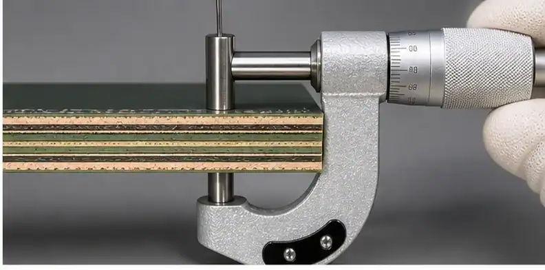
Quick Answer: Choose BT PCB thickness and layer count from package I/O density, plane needs, finished height, and warpage tolerance. Thin BT cores and prepregs support compact packages, but thinner construction increases handling and coplanarity risk, so the stack-up must balance routing, stiffness, and assembly yield.
Key takeaways
- Layer count follows I/O escape and plane requirements before cost discussion.
- Thin BT improves package height but raises warpage and handling sensitivity.
- Coreless BT belongs to ultra-thin packages and requires stronger process control.
- Thickness choices should be tied to copper symmetry and package acceptance limits.
BT stack-up work is easy to under-specify. A buyer may send Gerbers and a target thickness, while the supplier still needs to know whether the package needs a cored laminate, a very thin BT core, a coreless route, or a higher-stiffness low-CTE family. This article keeps the focus on mechanical and routing choices. For the earlier material-switch question, use when to choose BT over FR-4. To place this decision beside related material, application, and sourcing questions, use the complete BT PCB resource as the hub page.
Table of Contents
- How do you choose BT thickness and layers?
- What layer count does the I/O map demand?
- How thin can BT cores and prepregs go?
- Cored versus coreless construction
- How thickness changes warpage risk
- How stack-up choices affect cost
- A BT stack-up decision framework
How do you choose BT thickness and layers?
BT thickness and layer count should be chosen together because routing density and mechanical stability are linked.
A thin substrate can satisfy package height while making warpage harder to control. A higher layer count can solve I/O escape while adding lamination steps, cost, and process sensitivity.
| Stack-up question | Why it matters | Quote input |
|---|---|---|
| Layer count | Sets escape routing, reference planes, and build complexity | I/O map, impedance needs, power plan |
| Finished thickness | Controls package height and stiffness | Target thickness with tolerance |
| Core route | Cored and coreless builds have different process risks | Allowed construction and qualification need |
| Copper symmetry | Unbalanced copper can drive bow and twist | Layer copper weight and plane distribution |
Start the RFQ with package height, I/O count, ball map, impedance targets, and any coplanarity limit. A supplier can then propose a stack-up that is manufacturable instead of guessing from a finished-thickness line.
This article is not a material comparison. It assumes BT is already justified and asks how the construction should be built.
Buyer call: Select layers from routing need, then tune thickness for package height and warpage control.
What layer count does the I/O map demand?
Layer count follows the I/O map, escape routing, power distribution, and signal reference needs.
A simple memory carrier may require fewer layers, while a compact package with high I/O, multiple power domains, or high-speed interfaces can need additional routing and planes. Extra layers should solve a visible routing or electrical problem.
Ask engineering for the minimum layer count that routes the package with acceptable impedance, return paths, and power integrity. Purchasing should not reduce layers only to lower price if the escape strategy then becomes unstable.
For memory-specific layer decisions, see selecting BT for memory.
Evidence rule: Do not lock a layer count until the I/O map and reference-plane plan are reviewed.
How thin can BT cores and prepregs go?
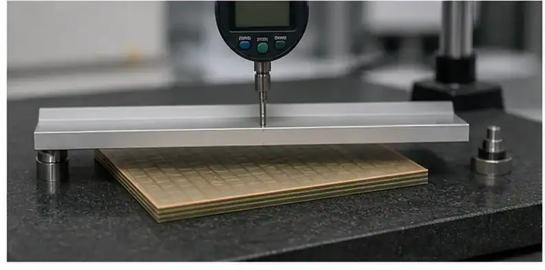
Very thin BT cores and prepregs exist, but availability and qualification must be checked by grade and supplier.
Public MGC material information describes thin BT CCL and prepreg options used for compact package substrates. Thin materials make package height easier to hit but leave less margin for handling, copper imbalance, and lamination movement.
The quote should state whether the requested thickness uses standard stock, thin-core material, special prepreg, or a supplier-specific package route. That statement protects schedule planning and repeat-order consistency.
A published thin-material capability does not guarantee the exact supplier has stock for the requested grade today.
Engineering gate: Treat sub-0.5 mm BT targets as a stack-up and sourcing review, not only a thickness number.
Cored versus coreless construction
Cored BT gives a central material reference, while coreless construction supports ultra-thin packages with tighter process control.
Coreless routes can reduce thickness and support advanced package density, but they make dimensional stability, handling, and warpage control more demanding. Cored construction may be easier to control when the package height allows it.
Ask whether the supplier is quoting cored, coreless, or a hybrid construction. The process choice should be visible before engineering approves the thickness and before purchasing compares prices.
Do not request coreless only because the package is modern. Use it when the height, routing, or package architecture requires that process.
Quote signal: Choose coreless only when the package benefit outweighs the added process and qualification burden.
How thickness changes warpage risk
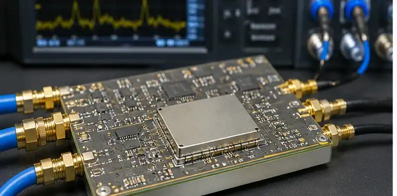
Thinner BT substrates are more sensitive to warpage, especially with asymmetric copper or uneven package loading.
Warpage is not just a cosmetic problem. It affects ball attachment, die placement, coplanarity, and final assembly yield. The risk rises when thickness shrinks while copper distribution, die size, or reflow stress remains high.
Provide copper weights, plane balance, finished thickness, component location, and any bow or twist limit. The supplier may suggest copper balancing, different material stiffness, or a revised stack-up.
Do not evaluate thin BT only by whether the Gerber can be fabricated. The package must also assemble within coplanarity limits.
Release check: A thin BT stack-up is acceptable only when warpage control is part of the release package.
How stack-up choices affect cost
Stack-up choices affect cost through layer count, material thickness, lamination complexity, finish, and inspection requirements.
More layers, special thin cores, low-CTE grade, coreless construction, and stricter warpage measurement all add cost drivers. QueenEMS covers the broader price logic in BT cost drivers.
Cost can be reduced by removing unnecessary layers, widening material options, or accepting a more available thickness. It should not be reduced by deleting the layer or stiffness that controls the package risk.
The safest quote comparison groups technical and commercial choices separately: required stack-up first, optional cost alternates second.
Document rule: Discuss cost after routing, height, and warpage boundaries are already stated.
A BT stack-up decision framework
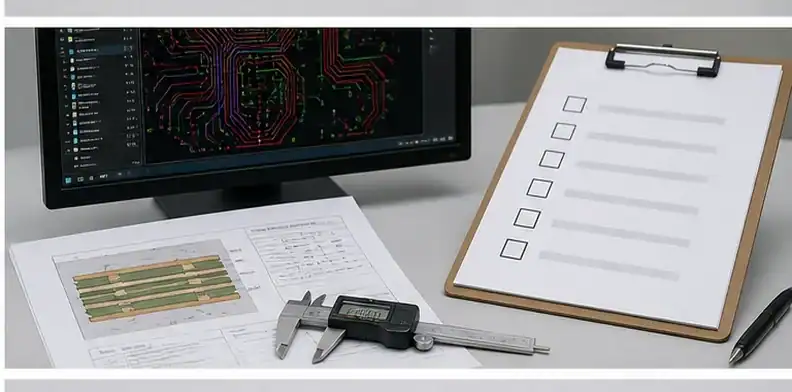
A practical decision framework starts with I/O, then height, then warpage, then supplier availability.
Use one review line for each item: I/O and reference planes define layers; package height defines thickness; copper symmetry and material stiffness control warpage; supplier stock controls schedule.
The final RFQ can include two options when possible: preferred stack-up and acceptable alternate. That lets QueenEMS check both fabrication risk and lead-time risk without changing the engineering intent.
For general HDI stack-up capability, the related HDI stack-up capabilities page can help when the design still behaves like a PCB rather than a substrate.
Design call: Release a BT stack-up only after routing, thickness, warpage, and availability have all been answered.
Stack-up field note for BT thickness: finished height should be treated as a package constraint, not only a board dimension. A thin target can be valid because the device must fit a module envelope, but the same thin target can create warpage, strip handling, and copper-balance problems. The supplier needs to know whether the value is a hard mechanical limit, a preferred goal, or an estimated number from a previous design. That status changes how aggressively alternatives can be proposed.
Use numbers as quote starting points, not as universal capability promises. A compact package discussion may compare 2-8 layers, a 0.20-0.50 mm finished-height window, 12-18 um copper on selected layers, or a 50/50 um line and space target only after the supplier confirms the exact BT grade and process route. Some buyers also add a bow/twist or coplanarity note such as 0.3% maximum, but that limit must be tied to package size and inspection method.
Layer count should be defended with routing evidence. A buyer who asks for fewer layers to reduce cost may create longer escape paths, poor return paths, or power-distribution weakness. A buyer who asks for too many layers can add lamination burden without solving a real electrical problem. The useful review compares ball map, I/O density, plane needs, impedance lines, and via strategy. Once those items are visible, the stack-up can be trimmed intelligently rather than randomly.
Coreless construction should be reserved for package needs that truly require it. It can support ultra-thin designs, but the supplier must control dimensional stability, handling, and warpage more tightly. A cored construction may be more stable when the height budget allows it. For a low-volume overseas buyer, the quote should name whether the proposed build is cored, coreless, or a thin-core route, and whether the same construction can be repeated for pilot production.
Project-specific checks
| Buyer check | thin stack-up record evidence | Use before quote release |
|---|---|---|
| finished height | thin core | Confirms the thin stack-up record basis before supplier comparison |
| prepreg choice | coreless build | Shows which thin stack-up record assumption needs engineering sign-off |
| stack-up escape route | reference plane | Prevents a quiet thin stack-up record substitution during pilot planning |
- Verify the finished height against the coreless build; that finished height pairing protects the thin stack-up record quote accuracy. If copper symmetry shifts, supplier wording changes; preserve layer count in the thin stack-up record so the finished height reviewer sees why coreless build stayed controlled.
- Map the thin core against the stack-up escape route; that thin core pairing protects the thin stack-up record assembly release. If construction warpage target shifts, supplier wording changes; preserve via route in the thin stack-up record so the thin core reviewer sees why stack-up escape route stayed controlled.
- Record the prepreg choice against the reference plane; that prepreg choice pairing protects the thin stack-up record customer approval. If panel handling shifts, supplier wording changes; preserve thickness tolerance in the thin stack-up record so the prepreg choice reviewer sees why reference plane stayed controlled.
- Compare the coreless build against the copper symmetry; that coreless build pairing protects the thin stack-up record supplier comparison. If layer count shifts, supplier wording changes; preserve package cavity in the thin stack-up record so the coreless build reviewer sees why copper symmetry stayed controlled.
- Separate the stack-up escape route against the construction warpage target; that stack-up escape route pairing protects the thin stack-up record pilot planning. If via route shifts, supplier wording changes; preserve routing channel in the thin stack-up record so the stack-up escape route reviewer sees why construction warpage target stayed controlled.
- Confirm the reference plane against the panel handling; that reference plane pairing protects the thin stack-up record shipment acceptance. If thickness tolerance shifts, supplier wording changes; preserve stiffness target in the thin stack-up record so the reference plane reviewer sees why panel handling stayed controlled.
- Flag the copper symmetry against the layer count; that copper symmetry pairing protects the thin stack-up record repeat-order control. If package cavity shifts, supplier wording changes; preserve pilot stack-up in the thin stack-up record so the copper symmetry reviewer sees why layer count stayed controlled.
- Freeze the construction warpage target against the via route; that construction warpage target pairing protects the thin stack-up record material continuity. If routing channel shifts, supplier wording changes; preserve finished height in the thin stack-up record so the construction warpage target reviewer sees why via route stayed controlled.
- Trace the panel handling against the thickness tolerance; that panel handling pairing protects the thin stack-up record quote accuracy. If stiffness target shifts, supplier wording changes; preserve thin core in the thin stack-up record so the panel handling reviewer sees why thickness tolerance stayed controlled.
- Review the layer count against the package cavity; that layer count pairing protects the thin stack-up record assembly release. If pilot stack-up shifts, supplier wording changes; preserve prepreg choice in the thin stack-up record so the layer count reviewer sees why package cavity stayed controlled.
- Name the via route against the routing channel; that via route pairing protects the thin stack-up record customer approval. If finished height shifts, supplier wording changes; preserve coreless build in the thin stack-up record so the via route reviewer sees why routing channel stayed controlled.
- Align the thickness tolerance against the stiffness target; that thickness tolerance pairing protects the thin stack-up record supplier comparison. If thin core shifts, supplier wording changes; preserve stack-up escape route in the thin stack-up record so the thickness tolerance reviewer sees why stiffness target stayed controlled.
- Screen the package cavity against the pilot stack-up; that package cavity pairing protects the thin stack-up record pilot planning. If prepreg choice shifts, supplier wording changes; preserve reference plane in the thin stack-up record so the package cavity reviewer sees why pilot stack-up stayed controlled.
- Tie the routing channel against the finished height; that routing channel pairing protects the thin stack-up record shipment acceptance. If coreless build shifts, supplier wording changes; preserve copper symmetry in the thin stack-up record so the routing channel reviewer sees why finished height stayed controlled.
- Verify the stiffness target against the thin core; that stiffness target pairing protects the thin stack-up record repeat-order control. If stack-up escape route shifts, supplier wording changes; preserve construction warpage target in the thin stack-up record so the stiffness target reviewer sees why thin core stayed controlled.
- Map the pilot stack-up against the prepreg choice; that pilot stack-up pairing protects the thin stack-up record material continuity. If reference plane shifts, supplier wording changes; preserve panel handling in the thin stack-up record so the pilot stack-up reviewer sees why prepreg choice stayed controlled.
- Record the finished height against the coreless build; that finished height pairing protects the thin stack-up record quote accuracy. If copper symmetry shifts, supplier wording changes; preserve layer count in the thin stack-up record so the finished height reviewer sees why coreless build stayed controlled.
Sources
FAQ
How many layers does a BT PCB need?
It depends on I/O escape, planes, and signal requirements. Do not copy another package’s layer count without checking the map.
How thin can BT PCB be?
Thin BT cores and prepregs are available from selected material families, but practical limits depend on grade, supplier stock, and warpage control.
Is coreless BT better?
Coreless BT is better for some ultra-thin packages, but cored construction may be safer when height allows it.
Does thickness affect cost?
Yes. Thin materials, coreless routes, extra layers, and tight warpage inspection usually increase cost.
Send QueenEMS your BT PCB thickness and layer count package
For a stack-up review, send the package outline, target finished thickness, I/O map, impedance needs, copper weights, and warpage limit through QueenEMS stack-up support. Those inputs can become a BT stack-up build route option set that separates required layers from optional cost or lead-time alternates.
Written by the QueenEMS Engineering Team
Upload your files today · Free DFM check before production · Ship worldwide
Get your PCB prototypes in as fast as 24 hours. We handle FR4, Rogers, and Flex up to 60 layers — free prototypes for 2–4 layer boards, no minimum order.
Just upload your Gerber + BOM — we source every part, assemble, and inspect (AOI + X‑Ray) so you don't have to chase suppliers. Boards ship in as fast as 24 hours.