

Quick answer: A Rogers PCB manufacturer should be able to identify the exact laminate grade and copper option, review the RF stackup before fabrication, explain the process controls for that material, and agree on measurable acceptance evidence. “Rogers PCB” is not a single specification: RO4003C, RO4350B, RO3003, and other grades differ in dielectric properties and processing needs. Send the grade, layer construction, operating frequency, impedance targets, and test requirements with the RFQ so suppliers quote the same board.
Rogers Corporation makes high-frequency circuit materials; a PCB fabricator turns a selected material into a finished board. That distinction matters when comparing manufacturers. A quote that merely says “Rogers material” leaves the grade, thickness, foil, bondply, and verification method open. The following checklist shows what to settle with engineering before choosing a fabricator—and what evidence to request before accepting the first build.
1. Choose the grade before comparing manufacturers
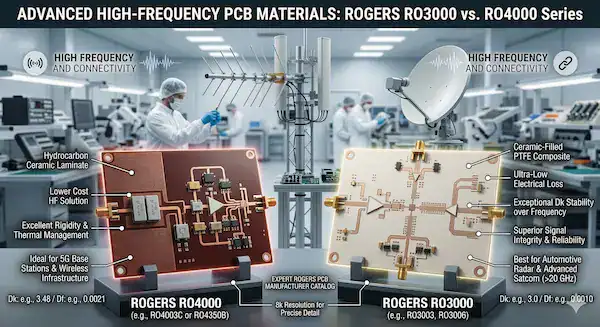
Start with the circuit requirement, not a generic “Rogers” label. RO4000-series materials are reinforced hydrocarbon/ceramic laminates designed for RF and microwave work; Rogers says they can be fabricated with processes closer to standard FR-4 than PTFE laminates. RO3000-series materials are ceramic-filled PTFE composites and call for PTFE-specific fabrication controls. Neither family is automatically the right answer for every frequency or product. Compare the specific grade and construction against your electrical, thermal, assembly, and cost limits.
| Grade | Material family | Process Dk at 10 GHz / 23°C | Typical Df at 10 GHz / 23°C | First question for the fabricator |
|---|---|---|---|---|
| RO4003C | Hydrocarbon/ceramic | 3.38 ± 0.05 | 0.0027 | Is the specified core, thickness, and foil available? |
| RO4350B | Hydrocarbon/ceramic | 3.48 ± 0.05* | 0.0037 | Does this exact construction meet the flame-rating requirement? |
| RO3003 | Ceramic-filled PTFE | 3.00 ± 0.04 | 0.0010 | How will PTFE handling and hole preparation be controlled? |
| RO3006 | Ceramic-filled PTFE | 6.15 ± 0.15 | 0.0020 | Has the design been modeled with the correct high-Dk grade? |
The figures above come from Rogers’ RO4000 data sheet and RO3000 data sheet. Their test methods and conditions belong with the numbers. If you are still deciding among laminate families, use the broader PCB materials guide as background; this article focuses on qualifying the Rogers-board manufacturer.
2. Lock the construction, not just the brand name
A manufacturer cannot confirm impedance or insertion-loss risk from a laminate family alone. The released stackup should identify each core and bondply, nominal dielectric thickness, copper weight and foil type, finished copper assumption, layer order, and controlled trace geometry. Rogers’ RO4000 data sheet distinguishes process Dk from design Dk; using the wrong value in a field solver can make a seemingly precise impedance target misleading. Agree on the model inputs and the measurement method before the artwork is frozen.
| Decision to freeze | Why it matters | Evidence to exchange |
|---|---|---|
| Exact grade and thickness | Changes dielectric properties, availability, and trace geometry | Approved stackup plus material part number |
| Foil profile and finished copper | Conductor loss and impedance depend on conductor geometry | Foil designation, copper build, and modeled assumptions |
| Bondply and lamination sequence | Controls final separation, registration, and mixed-material behavior | Lamination plan and approved substitute policy |
| Target impedance and tolerance | A nominal width without a test method is not an acceptance criterion | Reference layer, coupon design, method, and limits |
If the supplier proposes a different grade, foil, or bondply because of lead time, treat it as an engineering change rather than an equivalent purchasing substitution. Update the RF model, review thermal and assembly requirements, and approve a revised stackup before release. Our stackup review guide explains the general release checks; a Rogers build needs the material-specific fields above as well.
3. Ask how the shop controls the difficult steps
The relevant process depends on the selected laminate. Rogers describes RO4000 as compatible with many standard FR-4 fabrication processes and notes that it does not need the specialized via preparation associated with PTFE. Its RO3000 fabrication guidance, by contrast, calls attention to careful PTFE panel handling, drilling, surface preparation, and multilayer bonding. A shop experienced with one family should still explain its plan for the actual grade on your drawing.
Ask who approves the stackup and CAM changes, how material lots are identified, what drilling and hole-wall preparation will be used, and which lamination adhesive fits the construction. For a multilayer build, ask how registration and finished thickness will be checked. A capable answer is specific to your board: “we use a controlled process” without the grade, construction, and checks is not enough to compare two suppliers.

4. Put copper and impedance assumptions in writing
At RF and microwave frequencies, the conductor is part of the loss budget. Rogers offers LoPro versions of some RO4000 materials to reduce conductor loss, but that option changes the construction and must be modeled as specified—not silently substituted into an existing drawing. Trace width, etch profile, copper thickness, surface finish, and the dielectric design value can all affect the result. The supplier should confirm what it will build and what the engineer used in simulation.
Separate two questions: can the fabricator make the geometry, and will the completed line meet the agreed electrical limit? The first needs a DFM review of minimum widths, gaps, registration, and etch compensation. The second needs a defined test structure and method. A TDR coupon may verify an impedance range, but it does not by itself prove insertion loss at every operating frequency. If loss is critical, specify an appropriate RF test vehicle and acceptance method in the purchase package.
For a practical way to write layer pair, reference plane, coupon, and tolerance requirements, see our controlled-impedance specification guide. The important point for this RFQ is to tie each electrical requirement to a deliverable, not to assume “controlled impedance” means the same test scope to every shop.
5. Decide whether a hybrid stackup is justified
A Rogers-plus-FR-4 stackup may place low-loss material only where the RF circuit needs it. That can reduce premium laminate use, but it adds a material interface and may complicate thickness, registration, bondply choice, and repeat sourcing. Do not select hybrid construction from a price line alone. Mark the protected RF layers and reference planes, then have engineering review any change to their material or separation.
For example, on an illustrative six-layer RF/control board, the RF signal layer and its reference plane might drive the laminate choice while lower-speed control layers permit another material. Whether that particular stackup works depends on the actual geometry, frequency, thermal cycle, and adhesive system; it is not a generic recipe. Request both the electrical stackup and the proposed fabrication sequence before accepting the cheaper option. The separate Rogers–FR-4 hybrid cost guide covers quote assumptions in more detail.

6. Qualify the manufacturer with project evidence
A useful qualification conversation is about the proposed build, not a generic capability list. Ask the manufacturer to mark each requirement as accepted, requiring engineering review, or unavailable. Request a material-availability response, a preliminary stackup, a DFM exception list, and a first-article evidence plan. If the design is multilayer, the review should also name the lamination sequence and where inspection coupons will fit.
| Supplier question | Useful answer or document | Why it affects approval |
|---|---|---|
| Which exact laminate and foil will be purchased? | Grade, thickness, foil designation, lead time, and alternate policy | Prevents a generic “Rogers” substitution |
| What changes after CAM review? | Marked stackup, width/space changes, and approval owner | Protects the RF model from silent changes |
| How is the material processed? | Grade-specific drilling, hole preparation, and lamination plan | Exposes whether the shop understands the selected family |
| What evidence comes with the first lot? | Agreed coupons, inspection records, and exception disposition | Turns “quality” into an acceptance decision |
Certifications can be relevant to a regulated program, but a certificate alone does not show that a particular RF stackup will meet its electrical limits. Conversely, a supplier who raises a manufacturability objection early may be safer than one who accepts every requirement without identifying assumptions. Document who owns approval of material changes and what would trigger a new sample build.
7. Send an RFQ that makes quotations comparable
Send the same controlled package to each candidate manufacturer. At minimum, include fabrication files and drawing revision, layer stackup, grade and thickness per layer, copper and foil requirements, board outline, holes and vias, surface finish, operating frequency, impedance targets, quantity, and delivery expectation. Add an RF acceptance plan when line loss, phase, or other high-frequency behavior is a release criterion. If the requirement is not specified, ask suppliers to state the assumption rather than filling the gap silently.
| RFQ item | Owner-provided input | Supplier response to request |
|---|---|---|
| Material | Exact grade, core/bondply, thickness, foil | Availability and any proposed deviation |
| Electrical | Frequency, stackup, trace geometry, impedance/loss limits | Model assumptions, coupons, and test scope |
| Mechanical/assembly | Finished thickness, holes, finish, assembly thermal exposure | DFM exceptions and process limits |
| Commercial | Prototype and production quantities, required date | Material minimums, tooling, lead time, and included evidence |
Compare offers against the same approved construction. A lower unit price is not comparable if it excludes impedance coupons, assumes a different foil, or leaves a material substitute to be decided after purchase order. When an alternate is proposed, ask for two prices or a clearly marked deviation and route the technical choice back to engineering.
8. Accept the first build against agreed evidence
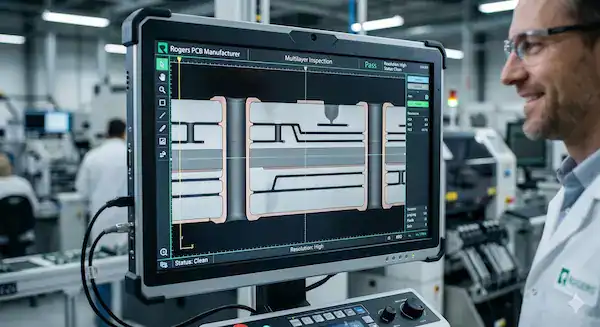
Before production, agree which first-article records matter for this design. Typical options include material identification, finished stackup or cross-section, hole-wall inspection, dimensional checks, and impedance coupon results. Add RF performance measurements only when the test method, fixture, frequency range, and acceptance limits are specified. No single inspection—especially a visual or X-ray image—can guarantee every buried interface or electrical behavior.
Record any deviation, its engineering disposition, and the approved production baseline. That makes the second order easier to control: the material, foil, stackup, process assumptions, and test scope are no longer implicit. If the first lot reveals a changed dielectric thickness or a trace-width adjustment, feed the as-built information back into the RF model before treating the design as production-ready.
Next step: review the exact build
To compare a Rogers PCB manufacturer meaningfully, send the laminate grade, stackup, Gerber files, impedance and RF requirements, quantity, and expected evidence with the inquiry. QueenEMS can review the proposed construction and identify items that need confirmation before quotation; feasibility, material availability, and test scope remain subject to the actual project. Submit the project details here.
Material references
- Rogers Corporation, RO4000 Series: RO4003C and RO4350B data sheet. Check its current revision, conditions, and thickness notes before release.
- Rogers Corporation, RO3000 Series data sheet. Published properties are typical values, not board-level acceptance limits.
- Rogers Corporation, RO3000/RO3200 fabrication guidelines. The fabricator should confirm the applicable process for the selected construction.
Upload your files today · Free DFM check before production · Ship worldwide
Get your PCB prototypes in as fast as 24 hours. We handle FR4, Rogers, and hybrid boards up to 40 layers in volume production, with advanced builds subject to engineering review — free prototypes for 2–4 layer FR-4 boards, no minimum order.
Just upload your Gerber + BOM — we source every part, assemble, and inspect (AOI + X‑Ray) so you don't have to chase suppliers. Boards ship in as fast as 24 hours.