
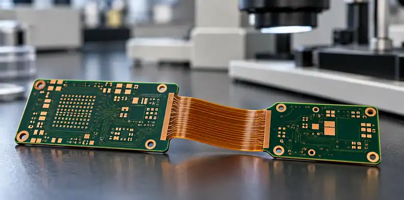
Quick Answer: Rigid-flex PCB release verification compares the supplier's proposed construction with the approved rigid and flex regions, bend definition, materials and inspection plan. Ask for evidence at the rigid-to-flex transition and resolve every deviation with the buyer's design authority before production begins.
A prototype can pass an electrical test while the next order still has unresolved material or construction assumptions. A release review gives the buyer, designer and fabricator one record of what was approved and what must be checked on the first lot.
What does rigid-flex PCB release verification require?
A supplier should confirm the construction by region, the bend requirements, the materials and the inspection plan against the released order. The buyer or design authority defines the product requirements; the supplier returns its manufacturing proposal and evidence. The buyer then approves the construction and closes any departures.
Start by assigning an owner to each open item. The design team should identify the mechanical envelope and critical electrical requirements. Purchasing should identify the revision and commercial scope. The fabricator should flag constraints and identify what it proposes to measure or inspect.
A released prototype can provide useful evidence, but ask whether the production construction, material sources and inspection scope match it. If they differ, the product team should decide which differences need further qualification. Record that decision with the order rather than leaving it in a separate email thread.
Does the proposed stack-up match each region?
Request a stack-up that identifies every rigid area, flex area and transition, including which conductive layers continue through the flex. Compare material identities, layer order and finished-thickness requirements with the released drawing. A supplier proposal that changes a layer or material should be treated as an explicit deviation.
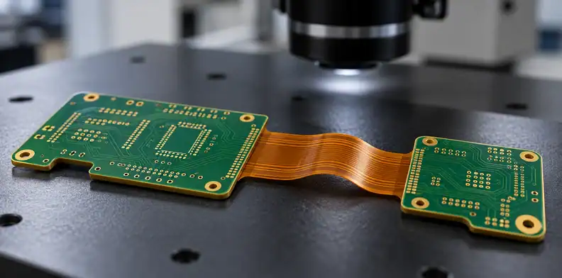
A board may have several rigid islands joined by flexible sections with different mechanical duties. A single overall thickness value may not explain those regions. Ask the supplier to label the areas consistently on the stack-up and the mechanical drawing, then identify where each measurement applies.
Review flex core, coverlay, bonding layers, rigid laminate and stiffeners where used. Make clear which dimensions are design limits and which are proposed manufacturing values. If the fabricator offers an alternate, ask for a marked comparison rather than a silent substitution.
The supplier stack-up signoff guide explains the general approval workflow. For this order, keep the rigid-to-flex transition and the flexible regions visible in that signoff.
Who defines and checks the bend zones?
The product team should define where the board bends, whether it bends during installation or repeatedly in use, and the available inside radius. The fabricator should review the proposed construction and keep-outs against that definition. Any conflict should return to the design authority before manufacturing data is released.
A bend definition should be tied to the actual enclosure and installation path. Identify the bend line, direction, available clearance and any nearby connector or stiffener. If repeated movement is expected, specify the conditions and test evidence needed for the product rather than asking the supplier to assume a generic cycle requirement.
Review holes, conductor paths, coverlay openings and stiffener edges near the bend against the design and order requirements agreed with the fabricator. Ask the designer to assess any proposed changes in the context of the intended bend.
Resin flow at the rigid-to-flex transition is covered in rigid-flex no-flow prepreg controls. Where the supplier's process needs a change near a bend, ask it to mark the affected areas. The designer should check the effect on mechanical clearance and electrical function, then approve the revision or reject the proposal. Keep the marked drawing with the order record.
Which materials and alternates need approval?
Identify the materials used in each region and require written review of alternatives that affect the approved construction. Depending on the design, the list can include flexible core, coverlay, adhesive or bondply, rigid laminate and stiffener. A similar material description alone does not establish equivalence for the application.
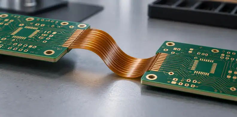
Record the approved material combination and require a documented decision before accepting a change. For example, Qnity's Pyralux GPL documentation describes a polyimide-film coverlay with adhesive for flexible and rigid-flex circuits. This example does not imply availability or approval for your order.
Ask for the proposed material identity, thickness where relevant, supplier or source, and any document that supports the order's stated requirements. When an alternate is offered, compare the properties that the product depends on and decide what qualification evidence is needed. A substitution that is acceptable for a fixed installation may need a different review for a moving hinge.
Send Gerber files, the region stack-up and bend drawing to QueenEMS for a quote and free DFM check. Include a BOM if assembly is part of the request; it is not required for a bare-board quotation.
What evidence should release the first lot?
Define a first-article package that connects each requirement to a feature, method and acceptance decision. It can include regional dimensions, coverlay registration, electrical results and a section at the rigid-to-flex transition where specified. Identify the applicable standard, revision and class in the order rather than assuming a default.
The matrix is a buyer's working tool. The evidence and stop conditions are recommendations to agree with the supplier; they are not a substitute for the applicable specification or a prescribed IPC form.
| Gate | Buyer defines | Supplier returns | Hold if |
|---|---|---|---|
| Region stack-up | Released layer and region drawing | Marked construction and deviation list | A region differs without approval |
| Bend | Location, static or dynamic duty, radius and clearance | DFM response against those conditions | A bend or keep-out conflict is unresolved |
| Materials | Approved identities and substitution rules | Construction material list and proposed alternates | A substitution is unidentified or unapproved |
| Transition | Inspection locations and acceptance criteria | Section or other agreed evidence tied to location | Evidence does not identify the required feature |
| Electrical | Nets, test scope and impedance requirements where applicable | Agreed test records and coupon results where required | The required test scope is missing |
| Dimensions | Outline and regional thickness limits | Measurements at agreed locations | A reported value is outside the agreed limit |
| Deviations | Authorized approver and disposition rules | Closed list linked to drawing revision | A departure remains open |
QueenEMS offers flying-probe testing and can build to IPC Class 3 when specified; confirm at quotation whether a stated class and test apply to your rigid-flex construction. The applicable board standard, class, test method and records should be specified for the project; the availability of a method does not mean every order receives every test.
What changes should return to the buyer after approval?
Require notification and a documented decision when a proposed change falls outside the approved construction or the order's granted authority. Material identity, transition construction, lamination route, coverlay, stiffener and inspection scope can affect the evidence used for release. Agree which changes require a sample, requalification or updated records.
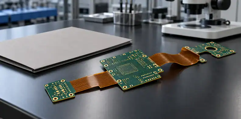
Changes to return for approval include material identity or source; lamination route or transition construction; coverlay or stiffener and its adhesive; drill or via structure in or near flex areas; panel layout affecting flex regions; manufacturing site; and inspection or test scope.
A change request should show the original and proposed conditions, the affected region, the reason for the change and the lots involved. It should also name the person or function authorized to approve it. Record a response against the current drawing revision so that purchasing, engineering and quality use the same baseline.
For a repeat order, ask whether the original material source and released construction remain available. If an alternate is needed, compare it with the original requirement before deciding whether the first-article plan remains sufficient. The outcome may be approval, additional evidence or a revised design.
What else do buyers ask about rigid-flex release?
Buyers need to settle who owns the bend definition, what a first article demonstrates and how later changes are handled. The questions below provide a starting point for the design and purchasing teams to agree the evidence and approval process with their supplier.
Who sets the bend radius?
The product designer or buyer defines the bend type, location and radius for the application. The fabricator reviews whether the proposed construction supports those conditions and should raise any conflict before release.
Should every first article include a bend test?
The required evidence depends on the product and purchase specification. If bend testing is needed, define the method, radius and cycles with the supplier. A section or electrical result alone should not be represented as proof of dynamic bend life.
Can a supplier change coverlay after approval?
A change outside the approved construction should be disclosed and reviewed under the order's change rules. The design authority can decide whether documentation, a sample or further qualification is needed for the application.
How much time does supplier verification add?
It depends on the construction, the materials and how complete the release package is. PCB lead time varies with material, so ask the supplier to show its verification steps, such as the DFM response, first-article evidence and approvals, in the schedule instead of assuming a fixed number of days.
Upload your Gerber files, region drawing and requirements to QueenEMS for a quotation and free DFM check. Add a BOM when you also need assembly.
Upload your files today · Free DFM check before production · Ship worldwide
Get your PCB prototypes in as fast as 24 hours. We handle FR4, Rogers, and hybrid boards, with standard builds up to 24 layers and higher layer counts subject to engineering review — free prototypes for 2–4 layer FR-4 boards, no minimum order.
Just upload your Gerber + BOM — we source every part, assemble, and inspect (AOI + X‑Ray) so you don't have to chase suppliers. PCB assembly typically takes 5–8 working days once all components are in stock. The confirmed delivery schedule is subject to your quotation.