
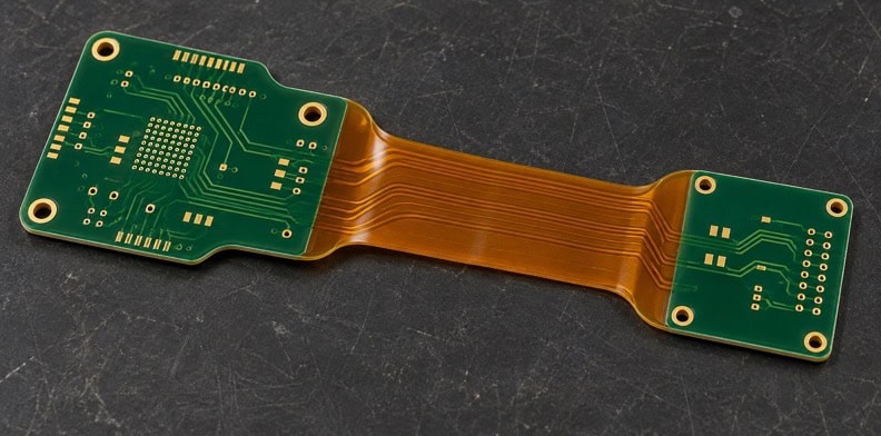
Quick Answer: A rigid flex PCB stackup should identify the construction in every rigid and flexible region, not just the total copper layer count. Give each region a section view keyed to the outline, showing continuing layers, coverlay and bonding boundaries, and finished-thickness requirements. Resolve differences between that drawing, the stackup table and fabrication files before approving the order.
A supplier can receive a complete set of copper files and still have to guess which materials stop at a rigid edge. The stackup drawing makes those decisions visible. This guide addresses how to prepare that regional construction definition before requesting a quotation, rather than how to design a particular microvia or approve a production lot.
What must a rigid flex PCB stackup drawing identify?
Identify every region with a different physical construction and show how its conductive and insulating layers relate to the board outline. Include rigid areas, flexible spans and any locally reinforced area that changes the section. A total layer count alone does not describe the material present at each location.
Use each marked section to show the materials that should be present at that location. A rigid island and its adjacent flexible span need different sections, even when some copper layers run continuously through both. Distinguish the global board construction from the local section a manufacturer must quote.
Epec’s published flex and rigid-flex stackup examples include stiffened flex builds and rigid-flex builds with air gaps. Those examples illustrate possibilities offered by that supplier; they do not establish an approved construction for your project or QueenEMS’s manufacturing scope.
Separate a design requirement from a choice left open to the fabricator. A controlled material identity belongs in the drawing. An undecided material should be marked for proposal, with the required function stated so the supplier can return a meaningful option.
The distinction becomes clearer if you read the stackup in two directions. From top to bottom, a section describes the local sequence of copper, dielectric and protective materials. Along the board, the regional views show which parts of that sequence continue and where others end. A conventional full-board layer table usually emphasizes the first direction. A rigid-flex definition needs both.
For a buyer reviewing an unfamiliar drawing, start with a single flexible connection between rigid areas. Locate that connection on the outline, find its section and follow its named copper layers into each rigid area. If the drawing cannot support that simple reading, the supplier may need a clarification before it can identify the intended construction. Adding more layer names to the global table will not resolve a missing regional view.
How do you connect region outlines to section views?
Use matching region identifiers on the outline, stackup table and section views. Place each section line where the construction it represents is clear, and identify its viewing direction. When an interface changes along the outline, add a view or detail that shows that change instead of treating one section as universal.
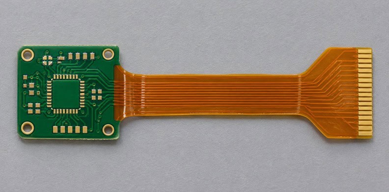
A section through the center of a rigid area may not show what happens where the rigid material ends. Likewise, a section through an uncovered flex span may omit a local stiffener. Pick views that explain those differences rather than adding sections simply to fill the drawing.
Identify the side from which the view is taken. A locally reinforced tail can otherwise appear correct while the support sits on the opposite side from the connector requirement. Keep the region labels stable when the artwork is exported, so a CAM question can name a precise location.
Record the section revision with the fabrication data set. A revised mechanical outline can change where a transition falls without changing the electrical netlist. Purchasing should therefore send a revision-matched package, with any preliminary view clearly identified.
Consider a hypothetical board whose flex span widens near a rigid island and has a support beneath only its connector end. A section across the free span describes the flex construction. A second section through the supported end describes the added local material. The outline supplies the missing information between those views: where the support starts and how far it extends. Neither section alone locates its edge.
Use a detail view when several boundaries would otherwise overlap on the page. A readable detail can separate the rigid edge, the coverlay edge and the support outline without prescribing their spacing. The required dimensions still come from the approved design and supplier review.
Which layers continue through each flexible region?
Show which named copper layers remain in each flexible span and which exist only in the rigid regions. Preserve the relationship to the full-board layer names rather than renumbering a local flex section without explanation. If layers separate into distinct leaves or sub-stacks, identify those groups and their separation boundaries.
The regional definition should let the reviewer follow a layer from a rigid section into the flex. A blank cell needs a stated meaning: absent, not applicable or awaiting a supplier proposal. Leaving those conditions indistinguishable invites a construction assumption during quotation.
For an illustrative construction, label a rigid island R, its flexible span F and a reinforced tail T. In R, the section shows the continuing flex core within the rigid build. The F section shows the continuing flex construction and protective covering, with the rigid material absent. In T, show the local support on its specified side. These are invented region labels for this explanation, not a QueenEMS stackup.
Trace the same continuing copper through R, F and T. Then trace the materials that stop or begin: the rigid build ends at the R-to-F boundary, while the local support starts at its own boundary near T. Show coverlay extent independently. The tail’s finished-thickness callout should identify whether it includes that support and adhesive. This lets a fabricator distinguish electrical continuity from changes in local thickness and stiffness.
For separated flex leaves, defer developed-length and installed-position detail to the bookbinder rigid-flex leaf definition guide. Separation by itself does not tell the manufacturer which leaf lengths or installed positions the design requires.
Check the reference-plane description as well as signal-layer continuity when controlled impedance is required. A named signal can continue electrically into a flexible region while the surrounding construction changes. The fabrication inquiry needs the applicable electrical requirement and the regions it covers, so the supplier can review the proposed geometry there. Copying one rigid-region cross-section across the full board could conceal that change.
Keep the layer names recognizable in the exported copper data. If the design tool produces a different file naming scheme, include a mapping between file names and drawing layer names. The mapping should answer a concrete question such as which copper file corresponds to the continuing flex layer. It should not leave the reviewer choosing between two plausible interpretations of an abbreviated file name.
Where do coverlay and bonding layers start and stop?
Show the intended extents of coverlay, rigid material and bonding layers on the regional sections, with boundaries tied to the outline. Distinguish these separate material edges even when they are close together. Ask the fabricator to identify any proposed change, then have the design owner approve the revised relationship.

Bonding layers are the prepreg or adhesive films that join parts of the construction. Their edge near a transition is a separate boundary from the coverlay edge. Identify the actual material and where it is intended to extend.
Altium’s discussion of rigid-flex stackups recommends stating the rigid-to-flex transition location explicitly in fabrication notes and seeking fabricator input early. Identify those interfaces before a supplier has to infer them from the artwork.
A line labeled “flex opening” can refer to different features. It might describe the opening in rigid material above a flex span or the boundary of a protective layer. Name the physical feature and show its relationship to the neighboring layers. Detailed coverlay pad openings and a supplier’s lamination process remain separate review tasks.
Read a transition detail as a description of finished materials. Which copper continues? Which rigid dielectric ends? What protects the conductors in the exposed flexible span? Does a locally bonded support begin nearby? These questions identify different physical features. Combining their boundaries under one unnamed line makes it difficult to tell whether a proposed CAM change affects insulation, local thickness or the rigid outline.
If a supplier recommends moving a boundary, request a marked section and corresponding outline location. A comment such as “adjusted for production” does not identify which material moved. The returned detail should make that change visible without suggesting that purchasing must select the fabricator’s lamination settings. Engineering approves the finished construction; the manufacturer explains the proposed way to produce it.
How should finished thickness be specified for each region?
State where each finished-thickness requirement applies and what surfaces define the measurement. Distinguish the rigid region, flexible span and locally reinforced areas where relevant. Identify whether a callout includes coverlay, copper or finish, and tie it to a marked location rather than using one ambiguous overall thickness note.
A finished-thickness requirement is different from a list of nominal material thicknesses. The design owner should identify the functional requirement; the fabricator returns the construction it proposes to meet it. Do not silently replace one with the other when comparing the supplier’s stackup.
A connector tail is a useful hypothetical check. If the connector interface depends on the completed tail thickness, identify the contact area and the surfaces that define that measurement. A note covering the free flex span may omit the local support, its adhesive or a surface layer present at the connector. Conversely, carrying the supported-tail value across the whole flexible span would describe a different construction.
Distinguish a local fit requirement from an overall assembly envelope. The first may apply only where the tail enters a connector; the second may concern the space available around a rigid island or support. Show both locations if both constrain the board. This avoids asking the fabricator to solve a mechanical fit question from a single board-thickness field in the quotation request.
Use the following definition sheet alongside the drawing. It is an editorial working aid, not a standard form or a description of QueenEMS’s internal process. Replace the prompts with your project’s controlled information.
| Definition field | Record for each region | Question to close |
|---|---|---|
| Region and section | Outline identifier, section line and viewing side | Does the view represent the named location? |
| Layer continuity | Named layers present and continuing layers | Are absent and undecided layers distinguishable? |
| Coverlay and bonds | Coverlay extent and bonding boundaries | Do section and pattern files agree? |
| Finished thickness | Requirement, measurement location and bounding surfaces | What exactly will the finished measurement include? |
| Open construction choices | Function required and item left for supplier proposal | Who approves the returned option? |
| Document identity | Drawing, stackup and fabrication data revision | Does the quotation name the same set? |
What should happen when the drawing and fabrication files disagree?
Stop the affected construction decision, identify the conflicting documents and obtain a design-owner resolution. State the governing-document order in the release package so the supplier knows how conflicts are handled. A convenient interpretation made during quotation should not become an approved change merely because it appears in the price.
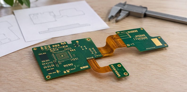
Consider an illustrative discrepancy: a section shows coverlay ending at the rigid edge, the material table shows it continuing beneath the rigid region, and the coverlay pattern has another boundary. These are conflicting definitions of one physical construction. None should be selected simply because it is easiest to manufacture.
The manufacturer can mark the difference and propose a resolution. The designer checks the electrical and mechanical consequences, then issues the corrected documents under an agreed revision. Keep the response with the quotation, and ask whether the change affects price or schedule.
Resolve the hypothetical coverlay discrepancy by naming the intended finished construction first. If the design owner chooses continuity beneath the rigid area, the corrected section, material table and pattern should all describe that choice. If the owner chooses termination elsewhere, the same documents must instead reflect that decision. A precedence order handles conflicts that have not yet been noticed; correct a known conflict in every affected document before the next order.
Once a supplier returns its proposal, use the rigid-flex release verification checklist for the later approval stage.
Frequently Asked Questions
Can I use a supplier’s standard rigid-flex stackup?
Use it as a starting proposal. Check its layers, materials, boundaries and finished regional requirements against your design before treating it as the approved construction.
Should impedance requirements appear on the stackup drawing?
State which layers, reference planes and regions carry the controlled requirement. The fabricator needs that information to review the local construction and geometry.
Does the stackup need to show stiffeners?
Show where a stiffener changes the local construction and which side it occupies. Keep its detailed material, adhesive and functional thickness requirements in the corresponding controlled drawing notes.
What changes after the supplier returns its stackup?
The design owner reviews the proposed construction and exceptions against the issued requirements, then records the approved revision before production release.
Send your released files for a quote and free DFM review.
For a rigid-flex PCB quote, send Gerber, regional stackup and section drawings. Mark region boundaries, continuing layers and open material choices.
For assembly, add the BOM and placement data. Confirm fitted positions, inspection and supported rigid-flex construction with your quote.