
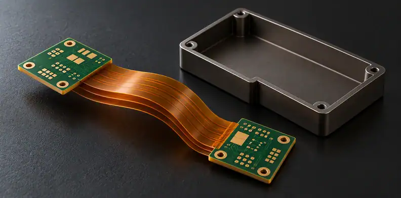
Quick Answer: For a bookbinder rigid-flex PCB, define each mechanically independent flex leaf or sub-stack by its layer membership, datum endpoints, approved developed length, tolerance and drawing revision. Check flat length and installed fit as separate states. A mock-up supports a geometry precheck; production-part fit and electrical checks need their own records, while repeated-bend qualification remains a separate gate.
Your product architecture is chosen, but the rigid-flex drawing still says only “bookbinder.” That word leaves the fabricator guessing which leaves separate, how their lengths differ and where each one must finish inside the enclosure. Resolve those details before releasing the fabrication order. The useful comparison is between each leaf's approved flat definition and its assigned installed position.
What makes a rigid-flex construction a bookbinder design?
A bookbinder construction uses separated flexible leaves or sub-stacks deliberately made at different developed lengths. A leaf can contain several copper layers; it is a mechanically independent part of the flex region. Bonded flex and unbonded loose-leaf construction describe different arrangements, so an unbonded region alone does not establish deliberate length compensation.
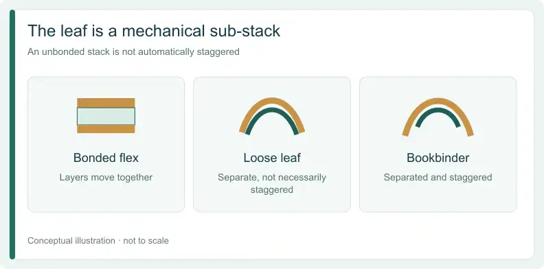
BestFPC's bookbinder construction explanation distinguishes separated sub-stacks with staggered lengths from loose-leaf layers that need not have that stagger. Sierra Circuits also discusses bookbinding in its rigid-flex design guidance. These are manufacturer explanations of a construction, rather than controlled lifetime trials.
In practice, supplier terminology can vary. Ask the drawing to show the copper layers belonging to each mechanical leaf, where the leaves are bonded or separate, and how they relate when folded. A stackup listing copper layers without that mechanical grouping leaves the object to be measured undefined.
Why do the leaves need different developed lengths?
In the same-direction folded arrangement described by the manufacturers, outer leaves follow longer paths around the bend. They therefore need additional developed length relative to inner leaves. The required lengths still depend on the actual endpoints, thicknesses, spacing and installed configuration; a generic bookbinder label cannot determine those dimensions.
BestFPC and Topfast's construction guide both describe this outward length progression. BestFPC also states that its idealized calculation assumes concentric bending paths and equal straight sections. However, those assumptions must not silently become a finished-part acceptance rule.
Have the mechanical designer define the actual lengths and tolerances with fabrication input. Preserve the intended fold direction and termination positions when reviewing them. This article supplies no offset equation, example allowance or universal bend-radius ratio: those would not define your particular installed geometry.
How should each flex leaf be defined on the drawing?
Give every leaf or sub-stack an ID and identify its copper-layer membership, separation boundaries and length datum. Record the endpoints, approved developed length and tolerance, fold direction, installed order, drawing revision and approver. Distinguish a designer-approved value from an initial buyer suggestion or an unapproved supplier deviation before treating the definition as released.
Use this author-proposed leaf definition card once for each mechanical leaf. Its blank fields are intentional: the project design supplies the dimensions, and the fabricator confirms the proposed construction. The card computes nothing and supplies no industry tolerance.
| Definition field | Project entry | Required origin or relationship |
|---|---|---|
| Leaf or sub-stack ID | Mechanical grouping on the layer map | |
| Copper-layer membership | Layers belonging to this leaf | |
| Bonded and unbonded boundaries | Defined zones on the drawing | |
| Length datum and endpoints | Named measurement references | |
| Developed length and tolerance | Approved design value | |
| Fold direction and installed order | Linked installed configuration | |
| Value origin | Buyer suggestion, approved design or supplier deviation | |
| Drawing revision and approver | Controlling project record | |
| Definition disposition | Defined, Hold or Clarify construction |
When is a leaf definition ready for release?
Mark Defined when the complete definition belongs to an approved revision with a named approver. Hold an identity gap if individual copper layers have been listed as independent leaves or a leaf’s copper-layer membership is blank. Similarly, a length without its measurement endpoints is a datum gap to hold. Provenance gaps also hold the definition while a value is still an initial buyer suggestion, an idealized estimate or an unapproved supplier deviation. If the leaves separate without an intended stagger, clarify the loose-leaf construction rather than assuming bookbinder compensation.
Send Gerber files with the stackup and flat and installed drawings for a quotation and free DFM review. Include the per-leaf definitions and unresolved deviations. Leaf construction, materials and process combinations require project-specific confirmation; add a BOM only if assembly is needed.
Why are flat length and installed position separate checks?
The flat drawing defines each leaf's developed length between specified references. The installed configuration defines where it must lie after folding, including alignment and clearance within the product. Supply both states on linked revisions. A satisfactory flat dimension or electrical result alone cannot demonstrate that the folded leaves occupy their required positions.
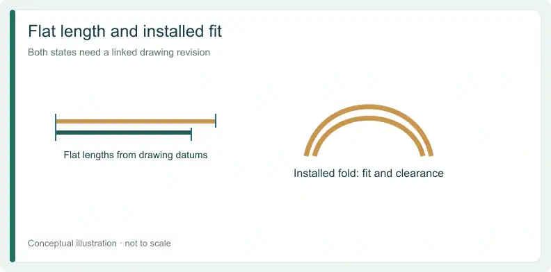
BestFPC recommends supplying the flat stackup together with the final folded configuration. Carry the leaf IDs between those documents so an inspection record identifies the same physical leaf in both states.
When reviewing a deviation, ask which state it affects. A revised endpoint or installed position may require the designer to reconsider the corresponding developed length. Record that decision on the controlling drawings before the supplier measures against an obsolete reference.
What can a mock-up prove before production parts exist?
An early paper, mylar or physical mock-up can help check the proposed geometry, form and leaf lengths within the enclosure. It is a precheck whose scope depends on what the model represents. Without the production copper, adhesive and materials, it cannot establish the electrical behavior or bending qualification of the manufactured rigid-flex.
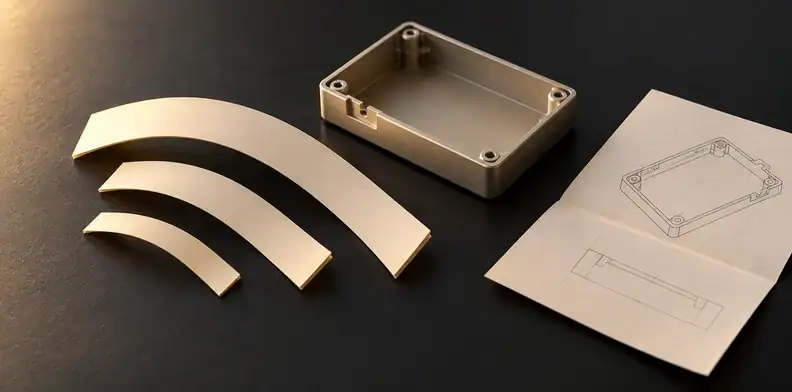
Sierra Circuits recommends early paper or mylar models in its flex and rigid-flex design guidance. Topfast likewise describes physical enclosure checks. Use these models to find an incorrect fold assumption or incompatible termination arrangement while drawings can still change.
Label the evidence as a model or mock-up, identify its revision, and state what was checked. However, passing that geometry precheck does not convert the model into a production specimen or establish fatigue life.
How should buyers read fit evidence before release?
Identify what was inspected, which specimen was used and which drawing revision controlled the comparison. Accept evidence only for the scope it actually addresses. A model, flat production part and installed production part answer different questions. Unknown specimen identity or a revision mismatch should hold the affected conclusion until the record is reconciled.
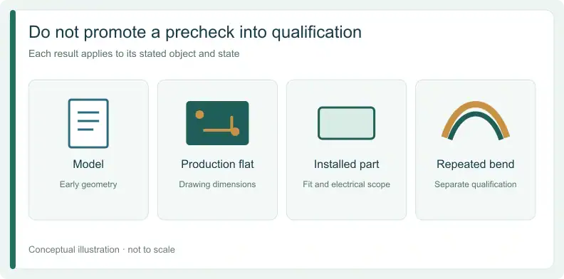
This author-proposed interpretation map classifies evidence by specimen, state and scope. Keep original buyer requests, agreed acceptance criteria and measured results as separate records beside it; a requested check is not a completed result. A blank specimen or revision cell means Hold for that row, never a pass. No industry threshold is supplied here.
| Evidence and state | Specimen / revision | What it supports | What remains unproved | Suggested disposition |
|---|---|---|---|---|
| Paper or mylar model | Early geometry range | Production materials and electrical behavior | Precheck only | |
| Physical enclosure mock-up | Form, fit and leaf-length precheck | Production conformance and fatigue | Precheck only | |
| Production part, flat dimensional check | Length conformance against the approved drawing by the agreed method | Installed alignment and clearance | Accept for stated scope if revision matches | |
| Production part, installed-fit and electrical checks | The agreed installed-fit and electrical scope | Repeated-bend life | Accept for stated scope if the records match | |
| Repeated-bend qualification | Its separately defined movement scope | Anything outside that qualification | Separate gate; route to rigid-flex release review | |
| No record or unknown specimen | No supported conclusion | The requested check | Unknown; Hold |
How should each result be named?
BestFPC connects individual leaf-length and compensation checks to approved drawings, while also listing separation, transitions and electrical integrity as distinct inspection objects. Preserve those distinctions when naming a result. For example, a passed flat-length record supports that dimension; it does not fill an absent installed-fit record.
Where does bookbinder fit review stop and other checks begin?
Leaf-length and installed-fit review establish only the agreed geometry and fit scope. They do not establish repeated-bend life, transition lamination quality or overall supplier release. Send movement requirements and first-lot evidence to the rigid-flex release review, and process questions at the rigid-to-flex exit to the transition lamination review.
For the wider release decision, see the guide on deciding what first-lot and repeated-bend evidence a rigid-flex release needs. For the transition process, see the guide on evaluating no-flow prepreg control at the rigid-to-flex transition.
Finally, keep the leaf card and fit record attached to the approved revision. Return an unresolved dimension, specimen mismatch or supplier deviation to its named approver before using it to release that leaf.
Frequently Asked Questions
Why can bookbinder flex leaves form a hump when flat?
The extra developed length assigned to an outer leaf has to occupy space before folding. A flat-state hump can therefore reflect the intended stagger. Its presence or size is not an acceptance criterion; check the actual drawing and required installed state.
Does unbonded loose-leaf construction always have staggered lengths?
No. Separation and deliberate length compensation are different features. Identify the leaf grouping, separation zones and lengths on the drawing. Confirm the supplier's terminology against those physical definitions instead of assuming that “unbonded” means the specified bookbinder arrangement.
Can an ideal bend calculation set the finished acceptance dimension?
An ideal estimate depends on its geometry assumptions. BestFPC's idealized calculation assumes concentric paths and equal straight sections. Your approved drawing must define the actual developed length, endpoints and tolerance with fabrication input; an estimate alone does not release the dimension.
Does bookbinder construction guarantee copper fatigue life?
No. A leaf-length definition or successful installed-fit check does not establish repeated-bend life. Identify any required product movement and obtain qualification evidence for that scope as part of the rigid-flex release review. A paper or mylar model supplies no copper-fatigue result.
To request a quotation and free DFM review, send Gerber files, stackup and the linked flat and installed drawings. Include the leaf definitions and open fit-evidence questions for project confirmation. Add a BOM only if assembly is also required.
Upload your files today · Free DFM check before production · Ship worldwide
Get your PCB prototypes in as fast as 24 hours. We handle FR4, Rogers, and hybrid boards, with standard builds up to 24 layers and higher layer counts subject to engineering review — free prototypes for 2–4 layer FR-4 boards, no minimum order.
Just upload your Gerber + BOM — we source every part, assemble, and inspect (AOI + X‑Ray) so you don't have to chase suppliers. PCB assembly typically takes 5–8 working days once all components are in stock. The confirmed delivery schedule is subject to your quotation.