

Quick Answer: Before ordering, a rigid flex PCB design should define the rigid and flexible regions, how the board must fit and bend, and the layer construction each region needs. Send the manufacturer a revision-matched layout, stackup and mechanical drawing, then review its proposed materials, fabrication assumptions and DFM feedback before approving production.
A rigid-flex design may look complete in its flat layout and still leave an unanswered question for fabrication: where does the flexible section end, and what must it do inside the product? The following guide turns those design choices into a package a board manufacturer can review.
When does a design need rigid-flex?
Consider rigid-flex when the product needs supported component areas connected by flexible sections that fit a defined three-dimensional space. Compare that construction with separate rigid boards and flexible interconnects using the enclosure, assembly sequence and service requirements. The right choice depends on the complete product, not the flat board outline alone.
Start with a mechanical model or a marked enclosure drawing. Show where each rigid area is mounted, where a flexible section must pass, and whether a technician will need to disconnect or replace parts. Installation-only folds and repeated flexing impose different requirements; state which applies.
Which regions are rigid and which are flexible?
Mark every rigid area, flexible area and transition on the board outline, then identify which layers continue through each region. Give the manufacturer a region map and a proposed stackup that use the same layer names. If material or thickness is still open, label it as a supplier proposal rather than an approved value.
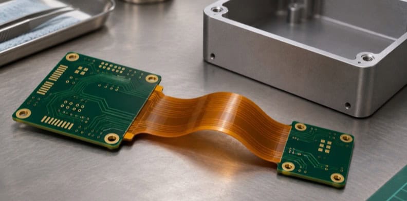
A single total layer count cannot describe a board whose rigid and flexible areas contain different layers. Show the region boundaries on the fabrication drawing and make the relationship to the layout files clear. Identify which surfaces carry components or connectors and where a stiffener is intended, if the design uses one.
Keep the map at the level needed to explain the construction. A manufacturer may recommend a different material or sequence during DFM; return the marked-up proposal to the design owner for review. A suggestion is not an approved substitution until both sides agree on the revision.
Where will the board bend, and how do you mark it?
Mark every bend location on the drawing and state how the flexible section is used: bent once during installation and then held in place, or flexed repeatedly in use. Include bend direction, the mechanical envelope and any project-specific fit requirements so the manufacturer can review the intended shape with the proposed construction.
A bend line in a layout is useful only when the drawing also explains its intended position in the assembly. Identify obstructions, mounting locations and the space available after folding. Share an enclosure model or a mechanical sketch when it helps the manufacturer understand the intended shape.
Altium’s rigid-flex guidance also lists layout practices the drawing should not contradict: avoid through holes in bend areas, especially for dynamic use; route conductors across bends with curves rather than sharp corners; on two-layer flex, stagger conductors on opposite sides; use hatched planes where possible; and allow extra flex length as a service loop. Confirm each choice against the proposed construction.
Set the bend radius with your engineering team and the manufacturer based on the board’s construction and use conditions. If the project calls for a standard or test method, identify the applicable edition and requirement before treating a number as an acceptance limit.
Do HDI or via choices change the build?
They can. Tell the manufacturer which connections must cross regions and identify any HDI or special via requirements in the proposed construction. The supplier needs the layer relationships and design data to assess the build. Ask it to flag assumptions about drilling, interconnections and materials before the design is released.
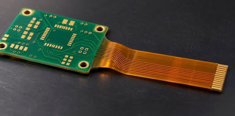
A via shown in the design file may connect layers that are present in one region but absent in another. The drawing and layout should identify the intended connection clearly enough for a fabricator to raise questions. The HDI rigid-flex design guide covers the more specific layer-mapping and via-build decisions.
A proposed build may require a change to a design feature. Record the affected layer, location and reason, then have the design owner decide whether the change preserves the intended electrical and mechanical function. Do not treat a quote as approval of an unreviewed alternative.
What files does a manufacturer need for a rigid-flex PCB quote?
Send a revision-matched fabrication data set, a drawing of rigid and flexible regions, the intended stackup, and the mechanical information needed to understand the final shape. Add the required finish, electrical test and quantity where known. Mark undecided requirements so the manufacturer can include its assumptions and questions in the proposal.
Gerber files and a drill file describe the circuit and holes; a fabrication drawing adds the requirements those files may not express. When the board’s fitted shape affects the design, include a mechanical drawing or model. Name each revision consistently across the files and explain any alternatives the supplier may propose.
| Buyer decision | Where to record it | Ask the manufacturer to return | Approval owner |
|---|---|---|---|
| Rigid and flexible regions | Board outline and region map | Questions or proposed changes to region boundaries | PCB design owner |
| Layer construction | Stackup and layer names linked to each region | Proposed construction and any material assumptions | PCB design owner |
| Bend location and use | Mechanical drawing, bend markings and use description | Confirmation that the proposed construction suits the stated use, or a proposed change | Mechanical and PCB owners |
| Finished requirements | Drawing notes for critical thickness, finish and test | Exceptions and items needing agreement | Project quality or design owner |
| Open decisions | List of items left to supplier proposal | Stated assumption for each open item | PCB design owner |
| File and revision set | Fabrication file list and drawing revision | Confirmation of the files used for the proposal | Purchasing or document owner |
The table is an editorial handoff aid, not an industry standard or a description of QueenEMS’s internal process. Its categories draw on Altium’s rigid-flex documentation, which discusses board regions, bending lines and fabrication drawing requirements. Assign the actual approver for your project.
Who approves the manufacturer’s proposal?
The buyer should identify an engineering owner who can review the manufacturer’s proposed stackup, exceptions and DFM changes before production. Purchasing can coordinate the response, but a technical change needs approval from the people responsible for the affected design requirements. Record the agreed proposal and revisions in the order package.
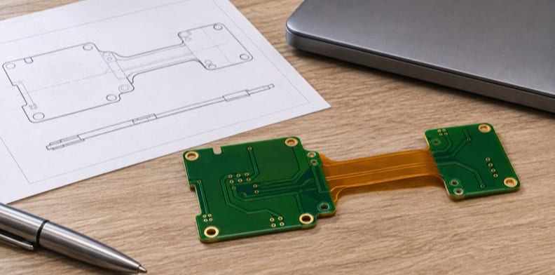
Compare the manufacturer’s response with the files it received. If the response names an alternative material, altered region or changed construction, ask what changed and why. The design owner can then decide whether the proposal meets the mechanical and electrical requirements or whether another option is needed.
Keep unresolved points visible. For example, a supplier may be able to quote a proposed stackup while a connector interface is still under mechanical review. Identify the assumption in the quote and close the fit question before giving an unconditional production release.
Before production release, use the rigid-flex release verification checklist. That review follows the design handoff described here and should use the actual construction proposed for the order.
Choose the checks appropriate to the project rather than assuming a fixed test package. QueenEMS offers AOI, X-ray, flying-probe, ICT and functional testing; which checks apply to a rigid-flex order must be agreed for that construction and scope. PCB lead time depends on material and project requirements, so ask for a schedule with the quote.
Frequently Asked Questions
A rigid-flex enquiry can start before every material choice is settled, provided the file package makes open decisions visible. The answers below clarify how to describe the design, coordinate mechanical review and keep revisions consistent while the manufacturer prepares a project-specific proposal.
What is a rigid-flex PCB?
A rigid-flex PCB combines rigid and flexible circuit regions in one construction. The rigid areas support parts or mounting points, while the flexible areas allow the board to fit a required shape. Each region can use a different layer construction, which is why the stackup is defined per region.
Do I need to choose every material before requesting a quote?
No. State known requirements and identify choices that are open to a supplier proposal. The engineering owner should review any proposed material and its effect on the intended use before approving the construction.
Should mechanical review happen before the fabrication enquiry?
Review the intended fit early enough to describe the enclosure, bend areas and mounting points in the enquiry. A later enclosure change can affect the drawing or construction and may require a revised supplier proposal.
Which file revisions should accompany a quotation request?
Send a consistent revision of the circuit data, fabrication drawing, stackup and available mechanical information. List any document that is preliminary so the manufacturer can state which files and assumptions its quote uses.
What is the difference between static and dynamic bending?
Static use generally describes a flex section bent for installation and then held in position; dynamic use involves repeated movement. Tell the manufacturer how the section will be used and identify any required bend radius or expected cycles in the project documents.
Upload a ZIP with your Gerber files and rigid-flex fabrication details to QueenEMS for a quotation and free DFM check. Include the current drawing revision, stackup for each rigid and flexible region, bend locations and whether the board bends during installation or repeatedly in use. Add the required bend radius and expected bend cycles, if specified. If you need assembly, add a BOM to the ZIP listing reference designators and manufacturer part numbers.
Send your released files for a quote and free DFM review.
Send Gerber, regional stackup and the bend drawing for review. Identify rigid and flex regions, materials and unresolved construction choices.
For rigid-flex assembly, add the BOM and placement drawing. Identify fitted regions, handling constraints and customer-supplied parts for scope confirmation.