
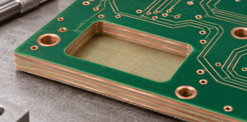
Quick Answer: A PCB cavity is a recess cut or formed into a circuit board, either open to a surface or enclosed between layers. Before requesting fabrication, identify which layers it spans, its contents and the files that describe it. Ask the manufacturer to review the construction and return exceptions before order approval.
A cavity can make room for a component, a solid copper heat-sink feature or another element, but those constructions do not all use the same manufacturing route. A quote package should make the planned build clear enough for a fabricator to ask the right questions, even when some decisions remain open.
What is a PCB cavity, and which types matter when ordering?
A PCB cavity is a recess cut or formed into the board, either open to a surface or enclosed between layers. For an inquiry, say which construction applies and what goes inside it. The manufacturer needs that use before it can assess the layer structure and production scope for your project.
Start by describing the physical result rather than choosing a process from a catalog. Is the area open to an outer surface, or closed between layers? Does it hold a discrete part, contain an insert or remain unoccupied? These distinctions affect the questions the supplier must answer.
| Intended construction | What the buyer should identify | Question to resolve with the supplier |
|---|---|---|
| Surface recess | Opening, intended floor and required finished geometry | Can the proposed feature and its surrounding layers be built as drawn? |
| Enclosed internal space | Layers above and below, and what will occupy or fill the space | Is an enclosed space acceptable in this stackup, and how will it be filled or sealed? |
| Component in a cavity | Part identity, intended position and electrical connection | Who supplies and places the part, and when? |
| Solid copper heat-sink feature | Intended insert or fill and its interfaces | Is that construction within the supplier’s quoted scope? |
This table is an editorial comparison, not an acceptance classification. Altium’s cavity guide and Summit Interconnect’s discussion describe cavities used for embedded parts, inset parts and other purposes. Summit also notes that air-filled cavities can raise mechanical-strength and moisture concerns, so state whether an enclosed space is meant to stay empty. Confirm the finished configuration with the supplier.
What should a cavity drawing show the manufacturer?
Give each cavity an identifier, show its outline and location relative to a stated board datum, and identify the layers or surfaces that define its intended depth. Reference the matching mechanical data and stackup revision. State which faces need exposed copper or other treatment, if those features are part of the design.
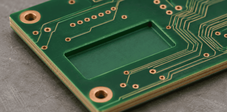
The fabrication drawing and exported layout must describe the same feature. A note such as “make a pocket here” leaves the manufacturer to infer the boundary, orientation and intended floor. Instead, point to the file and layer that carry the outline, identify the relevant stackup, and clearly mark any dimension or surface requirement that is still under review.
Altium recommends including cavity boundaries and the relevant starting and ending layers in the fabrication information. Altium and Summit describe cavity types using IPC-6012F; if your design uses that scheme, state the type on the drawing. For a routed cavity, specify the corner radius and confirm the part or insert fits. State outline and depth tolerances and the surface from which depth is measured. Ask for a marked-up drawing or written exception if a supplier proposes a change.
How does a cavity for an embedded component differ?
When a physically placed component is intended to sit inside a cavity, the inquiry must describe both the space and the part-to-board interface. Identify the specific part, its position and orientation, the contact locations, and whether the finished construction leaves the part exposed or enclosed within the board.
Timing matters as much as part identity. If the part will be enclosed, it must be in the cavity before the covering layers are bonded, so its placement belongs to the board build sequence, not a later assembly step. If the cavity stays open to the surface, the part can usually be placed afterwards. State which case applies and ask the supplier how it would sequence your design.
A formed resistor or capacitor built from materials in the stackup is a different design from a discrete component placed into a space. Do not assume that a supplier offering one construction can also quote the other. The existing embedded-passive HDI guide covers broader design and quote comparisons; this handoff focuses on the cavity and the physical part’s interface.
Show the part’s reference designator against the cavity identifier and provide the relevant part information and orientation. If placement coordinates or assembly instructions will be used, state their revision and which supplier is meant to use them. Confirm how the intended copper contacts correspond to the board files; do not assume an illustration alone defines that relationship.
What assumptions should accompany a cavity PCB quote?
State the quantity, board and cavity revisions, finished configuration and any material, inspection or delivery requirements already decided. List unresolved points and ask suppliers to identify the files and assumptions used in their quotes. A price based on one assumption should not silently become authority to manufacture a different version.
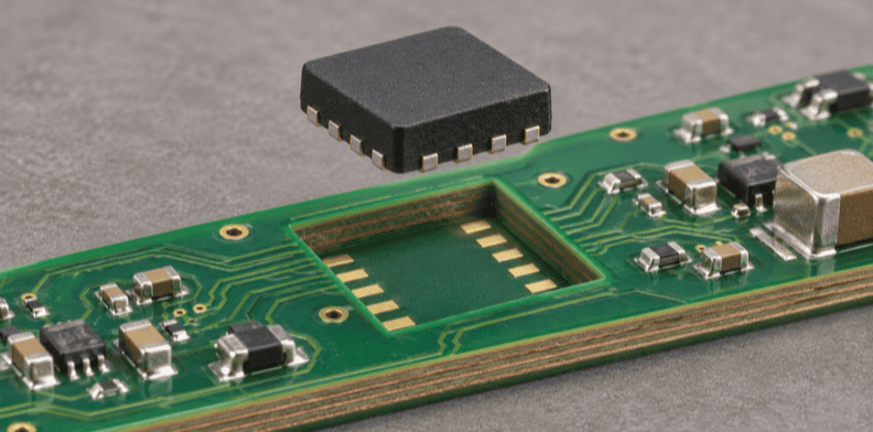
A supplier may quote a cavity as a board-only feature, while another may be asked to coordinate a part’s placement as well. Those are different scopes. Record whether parts are supplied by the buyer or sourced by the supplier, and name the organization responsible for placement. An enclosed part has to be placed during fabrication, so a separate assembler cannot add it later; a part in an open cavity can be a separate assembly step. Confirm suitability for the construction before comparing prices.
Who owns each decision between design and fabrication?
The design owner should define the intended board geometry and function, while the manufacturer should identify what it can build and any proposed exceptions. Purchasing can coordinate the exchange, but an engineering owner should approve changes affecting the design. Record the decision against the same cavity and document revisions.
| Item to connect | Buyer supplies or identifies | Ask the supplier to return | Decision owner |
|---|---|---|---|
| Cavity ID and location | Outline, datum and matching file revision | Questions or proposed changes to the feature | PCB design owner |
| Layer span and faces | Stackup and drawing notes for the intended surfaces | Construction assumptions and exceptions | PCB design owner |
| Part and interface, if used | Reference designator, part identity and connection intent | Placement scope, information gaps and proposed handoff | Design and placement owners |
| Open manufacturing choices | List of requirements open to a proposal | Quoted assumption for each open item | Design or purchasing owner |
| Inspection evidence | Required checks and the feature or stage they cover | Available evidence and any exceptions to the request | Project quality owner |
Adapt the matrix to your project; it is a working checklist, not an industry form or a description of QueenEMS’s internal process. Assign names and keep each supplier response with the corresponding quotation. If a part or cavity changes after the quote, identify the affected files and request an updated review before proceeding.
How should inspection and release be discussed?
Specify what must be checked, which construction or stage the check covers, and what record the buyer needs. A cavity drawing review, a bare-board electrical check and inspection after a component is embedded answer different questions. Agree on applicable checks with the supplier instead of assuming that one test covers everything.
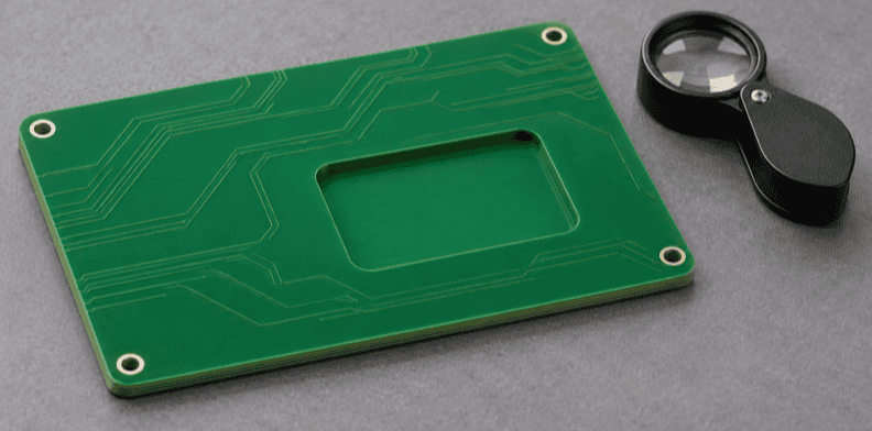
QueenEMS offers AOI, X-ray, flying-probe, ICT and functional testing; their applicability depends on the agreed order and construction. For a physically embedded discrete part, the embedded discrete PCB inspection guide explains how to relate inspection evidence to the specific feature. The cavity quotation should not promise a test or result that has not been agreed.
Before authorizing the order, compare the chosen supplier’s exceptions with the released drawing and stackup. Identify any unresolved material, cavity or placement question and who will close it. For PCB fabrication, lead time depends on materials and project requirements; request a schedule for the actual construction instead of relying on a generic turnaround number.
Frequently Asked Questions
These questions cover what a cavity describes, how it relates to an embedded component, who can place a part and which files should identify the feature. Use the answers to prepare a discussion with your manufacturer, then record the decisions for the specific construction in the agreed project documents.
What is a cavity in a PCB?
A PCB cavity is a recess cut or formed into the board, either open to a surface or enclosed between layers. A cavity can have different uses. Describe the finished geometry and use on the drawing.
Is a cavity the same as an embedded component?
No. A cavity describes a physical space or recess. An embedded component describes a part or function incorporated into the board construction. Some designs place a discrete part in a cavity; other embedded functions use different constructions.
Can a board fabricator also place the embedded part?
It depends on whether the part ends up enclosed. A part buried in the board has to be placed during fabrication, before the covering layers are added, so the fabricator must place it or coordinate that step. A part in a cavity open to the surface can be placed in a separate assembly step. QueenEMS must review the specific construction before confirming scope.
Which files should identify the cavity?
Use a consistent cavity identifier and revision in the fabrication drawing, relevant mechanical or layout data and stackup. Identify any preliminary file and ask the supplier to confirm which revision was used for its quotation.
Upload a ZIP containing your Gerber files and cavity fabrication details to QueenEMS for a quotation and free DFM check. Include the drawing revision, cavity identifier, intended layer span and unresolved questions. If you need component placement, add the BOM and relevant placement information to the ZIP and ask whether the full scope can be supported.
Send your released files for a quote and free DFM review.
Send Gerber, stackup and the cavity drawing for review. Mark cavity depth, exposed layers and open fabrication questions for the quotation.
If components must be placed in a cavity, add the BOM and placement details. Ask who places the enclosed parts and confirm the supported construction.