
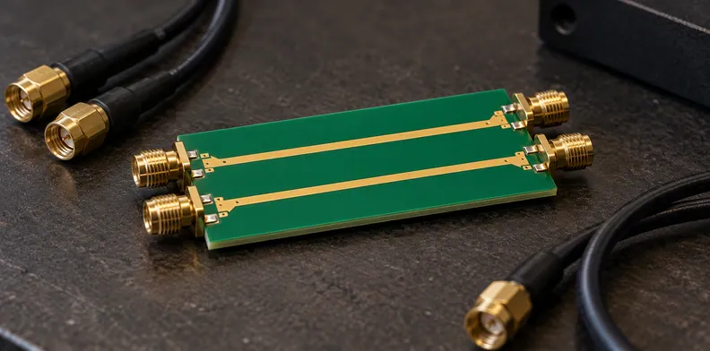
Quick Answer: A passing impedance result describes the tested line’s characteristic impedance; it does not say how much signal couples into a neighboring path. PCB crosstalk measurement acceptance needs a defined aggressor and victim, port map, observation end, mode, band or waveform, termination, reference planes and a customer-owned criterion. Without those fields, a coupling number cannot be compared reliably with the requirement.
A design can carry an impedance target in its stackup and a separate crosstalk requirement from the interface or system specification. A supplier can return a useful impedance report while the coupling requirement still has no agreed test object or acceptance record. Resolve that gap before release, including who will supply or review the evidence.
Why doesn’t a passing impedance report prove crosstalk acceptance?
An impedance result describes the characteristic impedance of the tested line or structure. Crosstalk describes coupling from an aggressor path into a victim path. The two records answer different questions, so PCB crosstalk measurement acceptance needs its own agreed quantity and evidence when the project has a coupling requirement.
An electrical continuity or isolation result also has a different purpose. It can address opens and shorts under the agreed test conditions; it does not by itself report the signal coupled between neighboring paths. Keep these reports alongside each other without treating them as interchangeable.
The customer may choose to accept the bare board on its impedance evidence and retain the coupling assessment in design validation. That is a valid division of work when the order makes the ownership explicit. It is different from claiming the impedance report proved the coupling requirement.
What physical test object does the coupling result describe?
Identify whether the result comes from a separate coupon or from accessible production paths. Record the drawing revision, layer, relevant parallel section and the specimen or lot to which the measurement applies. A result describes that object; the customer decides whether it represents the paths covered by the requirement.
A coupon may give the test team a defined structure and accessible ports, but its geometry must be compared with the design feature it is meant to represent. Layer position, path relationship, transitions and launch structures should be identifiable in the drawing or supporting record.
If the production net is measured instead, state the accessible endpoints and the structures included between them. A coupon result and a production-path result need not have the same scope. Do not transfer a result from one to the other unless the project owner accepts the transfer.
How should aggressor and victim ports be mapped?
Map each port to a physical line end, then identify the driven aggressor and the observed victim. Name the near or far end relative to the aggressor's driven end, and record unused-end terminations. State whether the requirement and result use single-ended or differential signals, including the intended pairing.
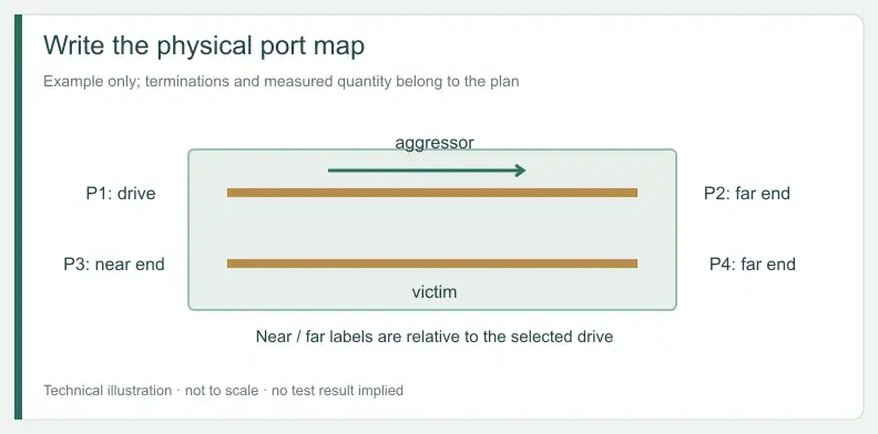
The Keysight 5989-5764EN application note describes a four-port arrangement for complete characterization of a differential pair, with a coaxial port at each end of each line. That describes one measurement arrangement for one pair; it does not prescribe a buyer record. The card below is a suggested record, not a standard form.
| Field | Record for the project | Basis |
|---|---|---|
| Record and test object | PCB revision, lot or specimen, coupon or production net, layer and drawing reference | Buyer definition |
| Aggressor and victim | Name each path and the driven port | Buyer definition |
| Port map | Port number to physical line end; pair the relevant conductors | Buyer definition; Keysight discusses four ports for one differential pair |
| Observation and mode | Near or far relative to the drive; single-ended or differential; customer-defined term | Buyer definition; near and far are named relative to the driven aggressor end |
| Terminations | Reference impedance of each instrument port, and the termination of any line end not connected to a port, as reported | Buyer definition |
| Domain and settings | Frequency range and points, or stimulus and edge; report settings affecting the noise floor | Buyer definition; Keysight discusses dynamic range and IF bandwidth |
| Measurement boundary | Calibration plane, included structures and de-embedding method/version or none | Buyer definition |
| Criterion and decision | Customer document, quantity and band, data format, approver; or “not agreed” | Buyer definition |
For a differential requirement, the pairing and the customer's named quantity must be clear in both the criterion and the result. A single-ended observation is not automatically the same quantity. Where several paths are involved, extend the map to every line end actually included rather than assuming the four-port example covers the entire structure.
Which band or waveform makes the result comparable?
Use the frequency range and points, or the time-domain stimulus and edge, defined by the requirement owner. The measurement record must describe the same domain and quantity as the criterion. A number without its band or waveform cannot be compared with the criterion, even when its aggressor and victim are identified.
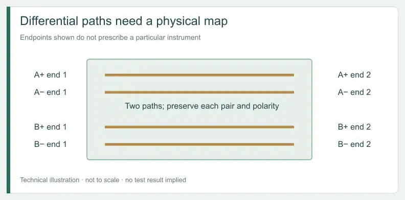
Keysight's note says measurements of low-level near-end and far-end crosstalk make test-system dynamic range important and discusses a VNA's intermediate-frequency bandwidth setting. Ask for relevant settings to be reported with the result. Those observations do not provide an acceptance value for the ordered board.
For a PCB quote or free DFM review, send the Gerber files, stackup or drawing and aggressor/victim definition. Whether a measured structure is feasible is confirmed for each project.
Where do the reference planes and fixture effects sit?
Record the calibration plane and identify whether launches, vias or connectors are inside the measured path. If the report uses de-embedding, name the method and version and send its applicability for customer review. The record should make clear which physical structures the reported coupling result includes or removes.
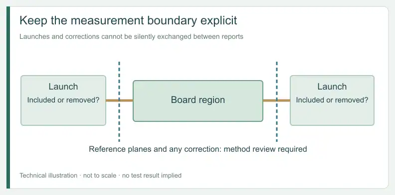
For example, a result that includes a launch describes a different boundary from a result reported after an agreed removal procedure. Neither should be called correct for the requirement until the owner compares its boundary with the criterion. A method's presence on the report does not establish that its removal is valid for this construction.
The related guide on deciding which insertion-loss and coupon evidence a backplane channel needs covers a different through-path measurement. Keep its loss requirement distinct from the aggressor-to-victim coupling record described here.
How should a buyer read the supplied coupling evidence?
Compare each item with the quantity and boundary in the customer criterion before assigning a disposition. Label a simulation as design evidence and a measured trace as test evidence. A result in the wrong mode or for the wrong path needs customer review; it is not automatically a failure or a substitute.
| Evidence supplied | Basis | What it shows and what remains open | Suggested disposition |
|---|---|---|---|
| Impedance or TDR coupon report | Test result | Tested-line impedance; not a coupling result | Available – context only |
| Simulated coupling | Design simulation | Modelled paths and assumptions; not a measurement of the shipped object | Customer review required |
| Measured single-ended near-end coupling | Test result | Reported path and near-end observation; other modes remain separate | Available – usable against agreed criterion if path, end, mode, band and boundary match; otherwise customer review required |
| Measured single-ended far-end coupling | Test result | Reported path and far-end observation; other ends remain separate | Available – usable against agreed criterion if path, end, mode, band and boundary match; otherwise customer review required |
| Differential result with pairing | Test result | Reported paired paths and term; scope depends on the port map | Available – usable against agreed criterion if pairing and term match; otherwise customer review required |
| Result including fixture | Test result | Coupling within the stated measurement boundary | Customer review required |
| De-embedded result | Processed test result | Result using the stated method; validity needs review | Customer review required |
| Customer criterion | Customer document | Agreed quantity, band, boundary and limit; not a measurement | If complete: governs the other dispositions. If absent or incomplete: missing – request before release |
| Spacing or design-rule report | Design evidence | Layout checks; not a coupling measurement | Available – context only |
For instance, a single-ended near-end trace may be complete on its own terms but still not meet the information needs of a differential criterion. Return it with the mode and path mismatch noted rather than labeling the product defective from the mismatch alone.
What must be agreed before the order is released?
Agree whether coupling stays with customer design validation or requires a measured structure within the order. If a measurement is requested, define its object, ports, mode, boundary, criterion and sampling, then confirm feasibility for the project. Hold a referenced requirement that lacks its criterion or has incompatible supporting evidence.
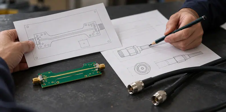
Record the decision in the order package. If impedance alone is the fabrication acceptance item, state who owns the separate coupling review. If a coupon or production path is to be measured, make clear which result is expected, how it relates to the design and who will review the returned data. Do not assume every production board receives the same measurement.
Frequently Asked Questions
Is a spacing check evidence of crosstalk acceptance?
A spacing check is design evidence, not a measured coupling result. The customer decides whether it is sufficient for the project’s requirement.
Can a single-ended near-end result stand in for a differential requirement?
Not without customer review. The modes and port definitions differ, so compare the reported quantity with the actual criterion.
Is every production board tested for crosstalk?
Not by default. Whether any boards or coupons are measured, which sample is used and whether the measurement is feasible are agreed for the project before release.
Is there a universal dB limit for PCB crosstalk?
Do not assume one. The interface specification or the customer’s engineering team defines the quantity, band, boundary and limit that the result is compared with.
Can simulation replace a measured coupling record?
The customer decides whether simulation is acceptable for the requirement. Identify it as design evidence and record its assumptions and scope.
For a PCB quote or free DFM review, share the Gerber files and stackup or drawing with the applicable coupling requirement. Add the BOM if assembly is also needed.
Upload your files today · Free DFM check before production · Ship worldwide
Get your PCB prototypes in as fast as 24 hours. We handle FR4, Rogers, and hybrid boards, with standard builds up to 24 layers and higher layer counts subject to engineering review — free prototypes for 2–4 layer FR-4 boards, no minimum order.
Just upload your Gerber + BOM — we source every part, assemble, and inspect (AOI + X‑Ray) so you don't have to chase suppliers. PCB assembly typically takes 5–8 working days once all components are in stock. The confirmed delivery schedule is subject to your quotation.