
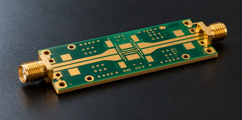
Quick Answer: For a passive RF line, the RF PCB power handling evidence these sources support is thermal: identify the dissipated-power inputs, the ground-plane temperature reference and the location along the line. Label each item as material data, a simplified steady-state estimate or a measurement on a stated construction. Breakdown, corona, peak and pulsed conditions, and mismatch limits need separate application-owned evidence.
A power figure on a drawing can hide several different questions. Will this particular line stay within the application's thermal limit at its real mounting boundary? Does the electrical-stress envelope cover its operating history? A material datasheet, a model and a measured board answer different parts of that decision. The application owner sets the operating conditions and criteria; the fabricator and any measurement provider confirm what construction and evidence they can supply.
What does power handling cover for a passive RF line?
RF PCB power handling is not one test result. For a passive transmission line, a thermal record addresses heating under stated conditions; electrical withstand, mismatch, pulse behavior and life are separate questions. A wattage without the construction, operating history and criterion leaves the buyer unable to decide what has actually been demonstrated.
Start by identifying the passive line and the conditions under which it must operate. A thermal calculation may be useful before a physical vehicle exists, but it is a prediction with assumptions. Similarly, a measurement on a different board may provide context without proving the delivered line. Separate these evidence classes before discussing whether a requirement is met.
The application owner decides which non-thermal failure modes need evidence and how they will be accepted.
Which operating conditions must the buyer define first?
The application owner must define the line revision, operating frequencies, power history and mounting or cooling boundary before a temperature estimate or measurement can be applied. State continuous or average operation separately from peak and pulse conditions. A fabricator can confirm the proposed construction, but should not invent the product's operating envelope.
A report for the correct material may still describe a different trace, stackup or mounting arrangement. Therefore, record the line identity, geometry and revision. If the power history contains peaks or pulses, keep their suitability open even when a steady-state estimate is available.
| Field | Supplied by | Basis | Disposition |
|---|---|---|---|
| Line ID and construction revision | Designer | Editorial suggestion | Stated / missing |
| Operating frequency | Application owner | Rogers note and column: loss context | Stated / missing |
| Power versus time | Application owner | Rogers note: steady state only | Steady-state input / peak or pulse remains open |
| Loss source and reference plane | Designer or measurement provider | Rogers note and column | Measured circuit loss / material Df only / missing |
| Width, length, dielectric thickness and thermal conductivity | Designer and material data | Rogers note | Stated / missing |
| Ground-plane temperature and cooling boundary | Application owner | Rogers note | Path stated / air or coolant alone leaves reference unresolved |
| Model assumptions | Person calculating | Rogers note | All four Rogers-note assumptions declared / undeclared |
| Segment or location evaluated | Person calculating or measuring | Rogers note | Input end or worst segment named / average only |
The application owner supplies the actual criterion; the record supplies none.
What does a steady-state temperature-rise estimate assume?
A simplified steady-state estimate describes a specified model, not every possible hot spot. Rogers' design note assumes heat flows in the thickness direction to the ground plane, treats RF insertion loss as conductor heat, assumes steady state, and uses uniform conductor and ground-plane temperatures. Each assumption matters when comparing the result with a real design.
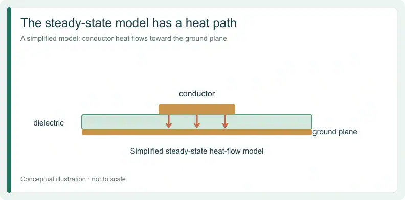
The Rogers temperature-rise note uses incident and transmitted power to estimate dissipated power over a line segment. Its other inputs are line width and length, dielectric thickness and dielectric thermal conductivity. The first three belong to the specific construction; thermal conductivity comes from the specific laminate’s data. None follows from a product family name.
The note presents its method as a conservative approximation, and that description holds only within the four stated assumptions. Do not turn that description into a guarantee for transient operation, a three-dimensional hot spot or a mismatched system. Instead, ask the person providing a calculation to identify the assumptions and explain where they may not represent the order.
Why is temperature rise referenced to the ground plane?
The temperature rise in the cited model is referenced to the ground-plane temperature, not directly to ambient air. To compare the result with an absolute project limit, the application owner needs a defensible ground-plane temperature for the real mounting and cooling path. A coolant or room reading alone does not supply that boundary.
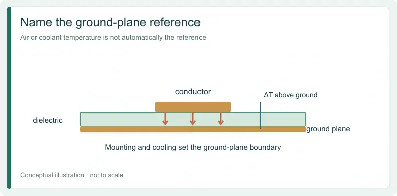
For example, a calculation can state a rise above a ground plane without establishing how hot that plane becomes in the assembly. So record the mounting interface, cooling condition and basis for the ground-plane value separately. If that value is missing, do not silently add the rise to ambient and call the result a measured conductor temperature.
An active amplifier has its own heat sources and paths; see the guide to budgeting GaN amplifier dissipation and the package cooling path under CW for that separate decision.
For a PCB quote and free DFM review, send Gerber files with the stackup or drawing. Material, geometry and any thermal-evidence scope are confirmed per project; PCB lead time varies by material.
Where along the line should heating be evaluated?
A temperature figure needs a location as well as a reference. In the Rogers line model, heating is greatest at the input end, while a value averaged over a longer segment describes that whole segment. Ask which point or segment a reported figure represents before treating it as evidence for the critical region.
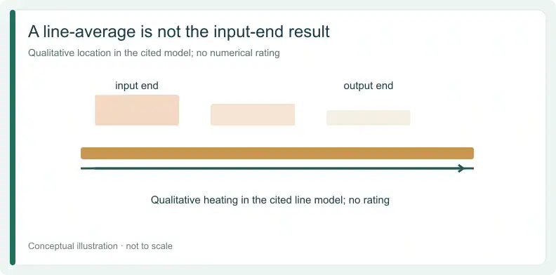
A whole-line average and an input-end estimate are different statements, even if both come from the same design note. The note discusses a mathematical convergence example; it does not prescribe a sampling pattern for every product. Instead, a project measurement plan needs to name its own observation locations and explain why they address the requirement.
If a report says “line temperature,” ask for segment and power-flow direction.
How should material data, estimates and measurements be labelled?
Material properties, calculated rise and physical measurements are three different kinds of evidence. A laminate's dissipation factor is an input about dielectric loss, not the complete circuit loss. A simplified estimate depends on declared assumptions; a measured rise describes its stated vehicle and conditions. None becomes a delivered-board rating merely because a number appears in a report.
The Rogers high-power materials column distinguishes dielectric loss from other contributors to insertion loss. It discusses thermal conductivity, which helps heat leave the circuit toward its heat sink, and separately the temperature coefficient of dielectric constant, which describes how Dk changes with temperature. Use the property that fits the question; neither measures the delivered line.
The note's worked example is a calculation under its stated model. The column also reports Rogers measurements on one microstrip line at 80 W applied, with a larger rise at 6.1 GHz than at 3.6 GHz, but does not disclose enough geometry, measurement method, cooling and reference detail to transfer them to another order. In short, neither example establishes a universal rating.
Which records support this order?
| Evidence item | Class | Reference and location | Relation to order | Criterion owner | Basis | Disposition |
|---|---|---|---|---|---|---|
| Laminate Df or thermal conductivity | Material property | Not a board temperature | Input to stated construction | Application owner | Rogers column | Input only |
| Rogers worked example | Calculated illustration (source model) | Above ground plane; model scope | Source example, not this order | Application owner | Rogers note | Not evidence for this order |
| Rogers reported 80 W example | Physical measurement reported | Method, geometry, cooling and reference undisclosed in column | Context only | Application owner | Rogers column | Not evidence for this order |
| Project estimate | Simplified estimate | State ground reference and segment | Match design revision | Application owner | Editorial suggestion | Estimate, assumptions declared |
| Measured rise, same construction | Physical measurement | State reference and observation point | Same construction revision | Application owner | Editorial suggestion | Evidence for stated construction only |
| Measured rise, representative vehicle | Physical measurement | State reference and observation point | Representative; differences listed | Application owner | Editorial suggestion | Evidence for stated construction only, differences open |
| Measured rise, unrelated vehicle | Physical measurement | As reported | Unrelated | Application owner | Editorial suggestion | Not evidence for this order |
| Breakdown or mismatch requirement without record | Project requirement | Not established by thermal record | Project-specific | Application owner | Editorial suggestion | Open requirement |
For the separate material-choice decision, see the guide on comparing RT/duroid grades when field concentration and heat flow drive the choice. An unrelated vehicle can be useful context; mark its differences instead of treating it as a pass.
Which power risks stay open without application evidence?
A thermal package does not establish breakdown withstand, corona or partial discharge, peak and pulsed operation, mismatch tolerance, or lifetime under power cycling. The application owner must decide which of these risks apply and identify the corresponding test object, evidence provider and acceptance criterion. Until that record exists, the item remains open.
A statement that a board is “IPC compliant” or “MIL compliant” cannot by itself establish a power limit. Ask which standard, edition, clause and test object the statement addresses, then compare that scope with the actual project requirement. A generic reference may describe a different property altogether.
Likewise, owning inspection equipment does not prove RF power qualification. If the application needs electrical-stress or life evidence, agree the scope and provider for that construction. A quote or DFM review can list an open item; it does not resolve it.
Frequently Asked Questions
Is a laminate datasheet enough to show RF PCB power handling?
No. Material properties are inputs; the circuit geometry, loss, reference temperature and construction-specific evidence also matter. A datasheet alone does not demonstrate the delivered line.
Does the published 80 W example mean my line can carry 80 W?
No. The Rogers column reports an example but does not disclose enough construction, cooling, reference and measurement details to transfer that result to your line. It is context, not a rating.
Does a steady-state estimate cover peak or pulsed power?
No. The cited estimate assumes steady state. Peak or pulse requirements need a separate project-defined basis and evidence appropriate to the operating history.
Can an IPC or MIL-STD reference replace power-handling evidence?
Only a named standard, edition, clause and test object can show what a particular reference covers. A bare standard name does not establish a passive-line power rating.
For a quote and free DFM review, send your Gerber files and stackup or fabrication drawing. Include the operating and evidence questions that need project confirmation. Add a BOM if assembly is also required.
Upload your files today · Free DFM check before production · Ship worldwide
Get your PCB prototypes in as fast as 24 hours. We handle FR4, Rogers, and hybrid boards, with standard builds up to 24 layers and higher layer counts subject to engineering review — free prototypes for 2–4 layer FR-4 boards, no minimum order.
Just upload your Gerber + BOM — we source every part, assemble, and inspect (AOI + X‑Ray) so you don't have to chase suppliers. PCB assembly typically takes 5–8 working days once all components are in stock. The confirmed delivery schedule is subject to your quotation.