
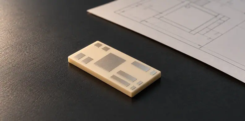
Quick Answer: Define the internal roof, floor and remaining passage of each buried LTCC cavity at named section planes tied to a datum, separately from the exterior profile and total thickness. Exterior profilometry shows only the outside surface, and a destructive section shows internal height only in one plane on one part, so neither establishes the minimum passage across the whole cavity. Acceptance values and any added method, such as CT, need project-specific agreement and construction-specific validation.
A drawing can specify the overall ceramic outline yet leave the channel inside it undefined. When LTCC cavity roof deformation matters, the buyer needs to know which internal feature is controlled, where it is assessed and what evidence is sufficient for release. The available study supports a limited comparison of exterior profiles and optical sections; it does not establish a universal manufacturing or inspection recipe.
What part of a buried LTCC cavity should the drawing control?
Control the internal roof and floor profile and the remaining passage at specified planes of the named buried cavity. A fired outline, pocket depth or overall thickness does not define those internal surfaces. The drawing must identify the construction and the locations at which the project will judge the geometry.
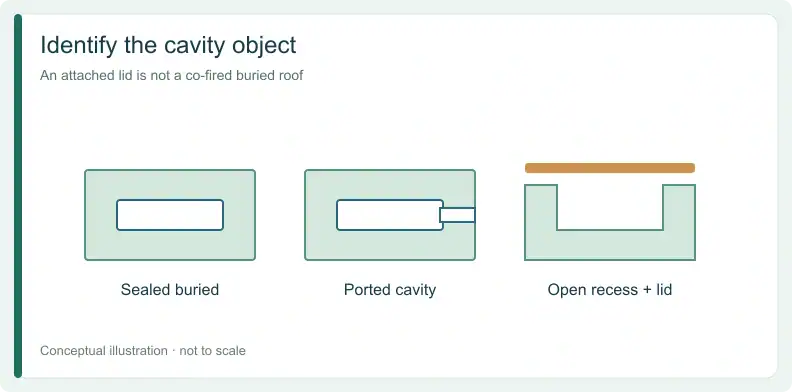
A buried cavity may be sealed or connected through a port. An open recess with a separately attached lid is a different object: a report about that attachment cannot simply be substituted for evidence about a roof formed within a co-fired stack.
The Fraley buried-cavity study examines coupon geometry and inspection, not the functional qualification of every product. It covered 16 test coupons in two sets of eight, in one tape system, and its only metallization was silver vias used as references for sectioning, so it does not represent a complete functional circuit or production capability. For the broader decision, see choosing between co-fired and post-fired ceramic routes.
Why can the roof shape change during lamination and firing?
The roof is formed inside a green stack and then densified, and the study identifies both lamination and sintering as challenges for buried-cavity shape. A finished exterior outline alone does not describe what happens to an internal roof, floor or passage. The drawing and evidence plan should therefore address the internal features that matter after the complete construction is made.
A 2015 finite-element model by Li and Wu simulates green-stack lamination around sacrificial material; it is a simulation rather than a post-fire internal measurement, and its scope does not include a complete conductor system. The Fraley coupon study examined process variations and reported mixed outcomes. It did not provide a general recipe for defect-free cavities.
Do not write a fixture, support material or firing profile into a requirement as though it automatically prevents deformation. The fabricator's proposed process and its applicability to the actual drawing require separate confirmation. If the technology itself is still open, see deciding between LTCC and HTCC technologies.
How should the drawing define roof, floor and remaining passage?
Name each cavity and section plane, tie the planes and reference features to a datum, and assign separate project values to the roof, floor and internal separation. Specify the exterior profile and total thickness separately. A project-owned value is needed wherever a result must support a release decision.
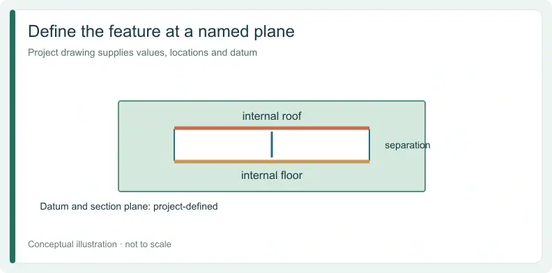
The Fraley study recorded maximum and minimum internal heights at sections and discusses the difficulty of defining reference points for irregular features. That supports making the datum explicit; it does not establish a universal tolerance.
| Drawing field | What to define | Basis |
|---|---|---|
| Cavity ID and revision | Name each cavity on the controlled drawing | Suggested buyer practice |
| Cavity type | Sealed buried / ported / open recess | Suggested buyer practice; open recess is a different object |
| Measurement planes | Locations tied to the drawing datum | Suggested buyer practice; study reports reference difficulties |
| Datum and reference features | Named design features; study used reference vias | Study method; via use is not mandatory |
| Internal roof and floor profiles | Project values at each named plane | Suggested buyer practice; the study recorded internal maximum and minimum heights at sections, not full profiles |
| Internal separation | Project maximum and minimum at each named plane | Study optical-section method |
| Exterior profile and total thickness | Separate outside values, not internal height | Study measured these separately |
| Unmeasured locations | List planes and volume not covered | Suggested buyer practice |
| Owner of each value | Buyer, supplier or joint decision | Suggested buyer practice |
Use “Defined” only when the feature, value, plane and datum are present. An ambiguous datum returns the requirement for clarification. Reject a mapping that uses an exterior-only value to claim an internal-roof result. Where a plane or volume has not been examined, record it as unknown rather than pass.
For a quote or free DFM review, send the drawing, stackup and cavity geometry card. Whether this construction can be supplied, and with which materials and process, is confirmed per project.
What can exterior profilometry tell you about a hidden roof?
Exterior profilometry records the outside surface. It can describe surface deviation over the cavity zone, but it does not directly show the inner ceiling or floor. Keep the exterior result tied to its scan location and specimen, and do not substitute it for an internal height requirement.
In the study, exterior profiles and subsequent optical sections were separate observations. A scan may be useful for the outside requirement on the same coupon; it cannot reveal how much open passage remains under the roof without additional evidence.
When a supplier returns an exterior trace, compare it only with the external feature and project limit it was intended to address. The existence of that trace does not close an internal profile item. If the drawing does not distinguish the two, fix the drawing before interpreting the result.
What does a destructive cross-section prove, and what does it miss?
A destructive optical section shows the internal maximum and minimum height in the examined plane on the sacrificed part. It does not establish the minimum passage at other planes, across the whole cavity volume or on other parts. The sample, drawing revision and section location must travel with the result.
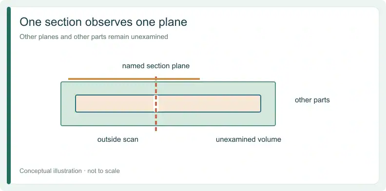
The study used silver reference vias to locate sections. This is a method used in those coupons, not a requirement that every design include the same features. The study also describes where sections fell relative to a design centerline; that is a location description, not a stated measurement precision.
Irregular walls and the choice of reference points complicate comparison. Before cutting a part, agree which plane and datum the result is intended to represent, how that specimen relates to the lot and what happens if a different plane remains unobserved.
How do you map each inspection result to a cavity feature?
Map each required internal feature to a named specimen, location and method. Record what that method establishes, what remains hidden and who owns the release or hold decision. A method described in another context is not validated automatically for the ceramic, metal and geometry in the actual construction.
The following map is a suggested buyer aid for matching an evidence record to a feature. Replace the illustrative entries with the drawing revision, lot linkage, project criterion and agreed owner. If the necessary value or location is missing, the row remains unknown.
| Required feature | Location, lot and revision | Method | Establishes | What stays hidden | Validation and basis | Disposition / owner |
|---|---|---|---|---|---|---|
| Exterior surface over cavity (offered as roof evidence) | State outside scan and specimen | Exterior profilometry | Outside surface only | Inner ceiling and other parts | Study method (coupon context); no standard cited | Cannot release an internal-roof requirement |
| Internal separation | Named section plane, sacrificed part, its lot and drawing revision | Destructive optical section | Internal maximum and minimum at that plane on that part | Other planes and other parts | Study method (coupon context); no standard cited | Compare at stated location / hold if outside value |
| Whole-passage minimum | Identify construction and required volume | CT or other non-destructive method | Unknown until validated | Unknown coverage and detection limits | No validation established in available sources | Hold until construction-specific evidence |
| Hermeticity, RF or flow | Named functional test object | Separate project test | Only its agreed functional scope | Other functions and untested features | No method established here | Separate requirement / application owner |
The cited cavity study supports exterior profilometry and destructive optical sections in its coupon context. It does not validate CT or ultrasound for the actual construction in your order. A proposed non-destructive method needs its own construction-specific evidence and coverage limits. Equipment availability alone does not establish that qualification.
What should both sides confirm before releasing the cavity build?
Before release, both sides should confirm the drawing values, section planes, datums, specimen and lot linkage, and treatment of unmeasured volume. Identify the decision owner for every open item. Functional requirements such as hermeticity, RF performance or flow need separate evidence; geometry at one section cannot replace those checks.
Read any supplier's design rule against the structure it actually covers. The TTM LTCC design guide discusses cavities defined as openings or through-holes. Its opening rules do not establish a safe span for a buried roof. Its floor and shelf requirements for openings are not roof-thickness or span limits either.
Agree whether an unexamined volume is acceptable for the intended product and what additional, validated evidence would be needed if it is not. A request for quote can identify these open questions; the resulting process, material and evidence scope still require project confirmation.
Frequently Asked Questions
Can X-ray CT confirm the whole buried cavity?
The available sources do not establish that. A CT method would need validation on the actual ceramic, metal and geometry, including its coverage and detection limits.
Is the minimum height in one cross-section the channel’s minimum passage?
No. It is the minimum observed in that plane on that sacrificed part. Other planes and parts remain unmeasured unless additional evidence covers them.
Do rigid fixtures or fugitive carbon prevent roof sag?
The cited study used fugitive carbon as a process variable, did not establish a defect-free recipe, and found the rigid fixture’s effect on deformation unclear. Suitability for a project needs separate evidence.
Do LTCC tape cavity rules give a safe roof span?
The cited guide discusses openings and through-holes, not an enclosed buried roof. Ask for rules applicable to the exact enclosed construction; no universal span is supplied here.
For a quote or free DFM review, share the Gerber files or drawing with the stackup and identify the cavity questions to confirm. Add a BOM only if PCBA assembly is also required.
Upload your files today · Free DFM check before production · Ship worldwide
Get your PCB prototypes in as fast as 24 hours. We handle FR4, Rogers, and hybrid boards, with standard builds up to 24 layers and higher layer counts subject to engineering review — free prototypes for 2–4 layer FR-4 boards, no minimum order.
Just upload your Gerber + BOM — we source every part, assemble, and inspect (AOI + X‑Ray) so you don't have to chase suppliers. PCB assembly typically takes 5–8 working days once all components are in stock. The confirmed delivery schedule is subject to your quotation.