
Quick Answer: Passing impedance and differential insertion loss does not establish the separate converted-mode response. Under the output-mode-first convention, Scd21 means differential input at logical port 1 and common output at logical port 2, while Sdc21 reverses the modes. Attach the physical port map, confirm the record contains that term or mapped complex data for a stated derivation, and let the application owner set the limit and frequency basis.
Your high-speed pair meets its impedance and insertion-loss requirements. The report may still say nothing about the conversion term your interface specification asks for, which is the core of PCB mode conversion acceptance. Before accepting a supplier or laboratory record, put the intended excitation, observation point and port map in the same statement. Then check whether the data actually supports that statement and who owns its acceptance criterion.
Why Can a Pair Pass Impedance and Loss Yet Still Convert Modes?
Impedance and Sdd21 insertion loss describe the differential path under their stated conditions. Mode conversion is represented by different, off-diagonal mixed-mode terms. A pass on the differential path therefore does not directly establish a converted-mode result. The acceptance record must identify the additional term the interface owner actually requires.
The distinction is between the mode launched and the mode observed. Teledyne LeCroy’s mixed-mode explanation places differential transmission and the two conversion directions in separate parts of the matrix. A passing differential-loss trace reports one part, not the converted component.
A separate timing question may also remain open; see why an impedance coupon may not settle differential skew. This article focuses on naming and interpreting the converted-mode record, rather than assigning a cause or a conversion limit.
Which Mixed-Mode Term Answers Your Release Question?
Start with the mode applied at the input and the mode observed at the output, then identify whether the observation is at the same end or the far end. Differential-to-common and common-to-differential conversion answer different questions. The correct PCB mode conversion acceptance term depends on the interface requirement, not a generic preference.
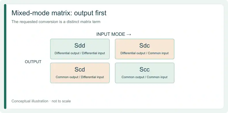
The Teledyne LeCroy mixed-mode explanation organizes the matrix by input and output mode: differential-to-differential and common-to-common terms, plus two conversion directions, differential in with common out (SCD) and common in with differential out (SDC). The first describes differential transmission or reflection when paired with the relevant port numbers; the conversion combinations describe changes of mode.
For example, Sdd21 addresses differential output at logical port 2 from differential input at port 1. Under the same convention, Scd21 addresses common output at port 2 from differential input at port 1; Scd11 asks about common output at the input end. The project must choose which question it needs answered.
How Do Scd21 and Sdc21 Differ, and Why Does Order Matter?
In the convention used by the cited sources, the first mode letter names the output and the second names the input. The first port number is the output logical port; the second is the input logical port. Scd21 and Sdc21 therefore describe different input and output modes, even though both use ports 2 and 1.
The Keysight balanced-measurement documentation explains this output-first address. Scd21 is differential input at logical port 1 and common output at logical port 2. Sdc21 instead starts with common input at port 1 and observes differential output at port 2.
Write the words next to the symbol in the requirement and check the provider's notation. If a specification says differential-to-common but uses Sdc21 under this convention, hold the address for correction. A mislabelled address cannot be accepted until it is corrected.
What Port Map Must Travel With a Mode Conversion Result?
A mixed-mode address is readable only when the logical ports are tied to the actual physical ports and their polarity. The record should identify the pair grouping, positive and negative conductors, viewing direction and which end is logical port 1. It must also say whether the requested observation is same-end or far-end.
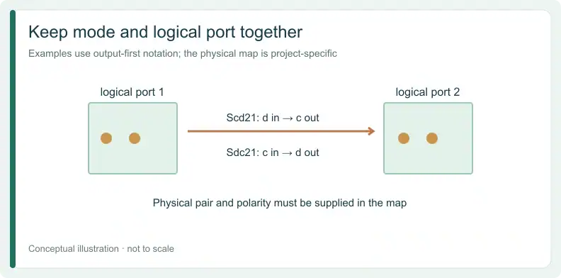
Keysight illustrates a balanced device with two logical ports formed from four physical ports. That example helps explain the mapping; its particular pairing is not a rule for your board. Draw or attach your own map, then keep the same mapping with the test record and its file identity.
| Field | What to record | Basis |
|---|---|---|
| Requested conversion in words | For example: differential driven at connector end, common observed at far end | Buyer suggestion |
| Output / input mode letters | For that example, c / d | Keysight and LeCroy output-first convention |
| Output / input logical ports | 2 / 1 for far end, or 1 / 1 for same end | Keysight output-first port convention |
| Physical grouping and polarity | Which physical ports form each logical port, including + and − | Keysight topology example; project mapping |
| Viewing direction and port 1 end | Drawing reference | Buyer suggestion |
| Reference impedance / normalization | As stated by the measurement provider | Record the method; sources give examples, not a universal rule |
| Quantity, units and frequency basis | For example, magnitude in dB versus frequency | Project-owned |
| Criterion owner | Named application role or document | Buyer suggestion |
| Disposition: Addressed — words, mode letters, logical ports and physical map agree. Ambiguous: hold — pairing, polarity or port 1 end is missing. Contradictory: correct before quoting — for example, the words say differential-to-common but the symbol is Sdc21. Not requested — the project does not need this term. | ||
An “Addressed” disposition means the question is defined, not that its limit has passed.
For a quote and free DFM review, send your Gerber files with the stackup or fabrication drawing. Attach the address sheet so the requested term stays with the design files.
Is the Delivered Data Enough to Support Scd21?
A scalar differential insertion-loss plot does not contain the requested converted-mode term. The record must either contain the correctly addressed term or provide mapped complex single-ended data, magnitude and phase, covering every physical port in the map, from which a stated method can derive it. File identity, port grouping and reference basis must accompany the result.
Keysight describes deriving balanced parameters from single-ended complex measurements. It also describes a true-mode stimulus method as a distinct approach. The Teledyne LeCroy explanation sets out its passive, linear, time-invariant interconnect scope. These sources show that both approaches exist; they do not make one method mandatory for every passive board.
Before applying this table, record the data-file identity, actual method, topology and pair map used in any calculation. Assign unresolved source, load and common-return conditions to the application owner rather than guessing them from a plot.
| Delivered record | Requested term? | Derivable by a stated method? | Usually missing | Disposition |
|---|---|---|---|---|
| Scalar Sdd21 or insertion-loss plot | No | No | Converted quadrant, phase and port map | Insufficient |
| Named Scd21 trace, magnitude only | Magnitude, if the map matches | No re-derivation from magnitude alone | Phase, data file or map confirmation | Contains magnitude: verify address |
| Mapped complex single-ended multiport data | Not directly | Yes, with a stated method in the cited passive LTI scope | Method and reference basis | Derivable with stated method |
| Mixed-mode data from stated true-mode stimulus | Yes, if the address matches | Not applicable | Map and reference basis | Contains: verify address |
| No file identity, method or map | Unknown | Unknown | Identity, method and mapping | Unknown: request record |
A magnitude trace can contain the requested quantity without supplying the phase data needed for a new derivation. Conversely, a complex data set can support a derivation only if its mapping and method are clear. Neither disposition decides whether the application limit is met.
Who Owns the Limit, Frequency Basis and Reference Conditions?
The interface or application owner sets the conversion criterion, its units and the frequency basis. The measurement provider states the reference impedance and normalization actually used. These details travel with the result so the parties compare the same quantity under the same conditions; a borrowed number is not an acceptance specification.
The LeCroy article uses 50-ohm driving and termination impedances in its single-ended example. Treat that as an example, not a mandatory value for every report. Ask the provider to identify the basis used, then have the application owner decide whether it matches the interface requirement.
For the neighboring transmission question, the separate guide on specifying Sdd21 transmission and port pairing for a backplane channel covers that release scope. PCB mode conversion acceptance still needs its own named term, map and criterion. Do not copy an unexplained single dB figure across an arbitrary band.
What Can This Record Not Tell You About the Assembled System?
A converted-mode record describes the interconnect network under the stated reference conditions. It does not by itself predict behavior with the actual driver and receiver, source or load mismatch, or electromagnetic compliance of the assembled product. Those conclusions require their own application-level evidence and criteria.
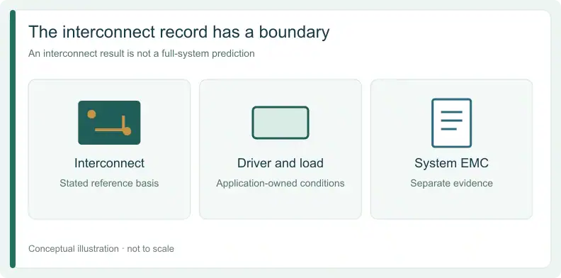
The terms are defined under the reference basis the provider states, not under the product’s actual driver, receiver and terminations. Preserve the observed mode, end and basis in the report rather than treating them as a system prediction. A record without the applicable source and load conditions leaves that system question open.
Keep the acceptance decision proportional to the evidence: hold a contradictory address, request missing data, or proceed to a quote and DFM discussion with the definition attached. Proceeding to that discussion is not a pass on the converted-mode criterion.
Frequently Asked Questions
Is Scd21 the same as Sdc21?
No. Under the output-mode-first convention used here, Scd21 is differential input at logical port 1 and common output at port 2. Sdc21 has common input and differential output at those ports.
Is there a standard dB limit for PCB mode conversion?
The cited sources do not give a universal acceptance value. The interface or application owner sets the required quantity, units and frequency basis for the project.
Does the measurement need simultaneous true-mode stimulus?
Not necessarily. The cited documentation describes both derivation from mapped complex single-ended data and a true-mode stimulus method. Record which method and reference basis were used.
Does a good conversion result mean the product will pass EMC?
No. An interconnect result under stated reference conditions does not by itself establish compliance of the assembled product. EMC needs its own application-level evidence.
For a quote and free DFM review, send Gerber files with your stackup or fabrication drawing, including the requested term and port map. Add a BOM if assembly is also required.
Upload your files today · Free DFM check before production · Ship worldwide
Get your PCB prototypes in as fast as 24 hours. We handle FR4, Rogers, and hybrid boards, with standard builds up to 24 layers and higher layer counts subject to engineering review — free prototypes for 2–4 layer FR-4 boards, no minimum order.
Just upload your Gerber + BOM — we source every part, assemble, and inspect (AOI + X‑Ray) so you don't have to chase suppliers. PCB assembly typically takes 5–8 working days once all components are in stock. The confirmed delivery schedule is subject to your quotation.