
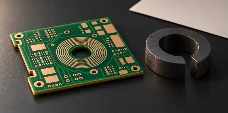
Quick Answer: First distinguish a laminated magnetic inlay from a bonded plate or external core. Name the material manufacturer, grade and family, with data for the intended conditions, then fix its shape and position in the released stackup. Get written confirmation of a named integration route for that combination and agree the pilot evidence; if these are unknown, hold or use a fallback. The public sources reviewed do not show completed reliability for the cited developer program.
A proposal for PCB embedded magnetic material may describe a laminated insert, a plate attached to a finished winding board or a core assembled outside it. Those are different constructions. Before committing to an inlay, establish whether a supplier has confirmed the exact material, geometry and route in writing, and which evidence will come back from a pilot. A research example is useful context, not a current supplier offer.
Is it a laminated magnetic inlay or a bonded magnetic plate?
A laminated inlay is placed within the stack before lamination; a bonded magnetic plate is attached to an already built winding board. An external core is assembled outside the board. Classify the construction first, because a result on one arrangement does not establish the route or evidence for another.
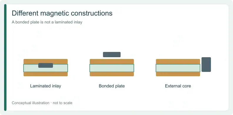
The AT&S developer presentation hosted by PSMA (2021) shows a historical resin-and-ferrite inlay and an illustrative section within a board. A separate 2018 conference paper describes glued magnetic plates without further moulding and proposes, but does not test, later PCB lamination. Neither establishes a current named route for your order.
| Construction claim | What identifies it | Example context | What it does not establish |
|---|---|---|---|
| A: Laminated inlay | Magnetic material placed before lamination; named material and a cross-section at the inlay | AT&S developer presentation shows a historical inlay section | Your grade, route or current availability |
| B: Bonded plate | Magnetic plates attached after the winding board, without lamination of the magnetic material | HAL research paper describes glued plates | Lamination compatibility |
| C: External core | Core fitted around or onto a finished winding board | Separate planar-transformer design scope | An inlay route |
| D: Narrated or unverified | Compatibility asserted without enough named material, route and section evidence | CPES research video, reviewed from narration and sampled frames | A qualified route for the order |
A supplier's statement can move from unverified to a specific construction claim when it names the material and route and provides appropriate evidence. It does not become a qualification merely because a cross-section resembles a published example.
Which magnetic material identity must be named before RFQ?
A material family is a starting description, not an orderable identity. Ask for the manufacturer, current grade, datasheet and conditions relevant to the intended use, then put that identity under change control. A published comparison of anonymous or nominal materials cannot select the grade for a particular inlay.
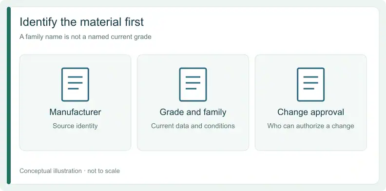
The developer presentation distinguishes resin-metal, resin-ferrite and sintered-ferrite families. Its comparison values are nominal and anonymous; they cannot be copied as a specification for a different supplied material. Request the material source and its current data rather than identifying the insert only as “ferrite.”
Record who can approve a substitution and what must be re-evaluated if the manufacturer or grade changes. Until the material is identified and the fabricator has confirmed its applicability to the proposed route, the inlay remains a feasibility question rather than a released construction.
What inlay geometry and position must the stackup fix?
The released stackup must locate the inlay and define its shape, thickness and relationship to surrounding layers. These are project drawing values, agreed with the fabricator for the named material and route. A published section can show what one developer built, but its geometry does not become a rule for your board.
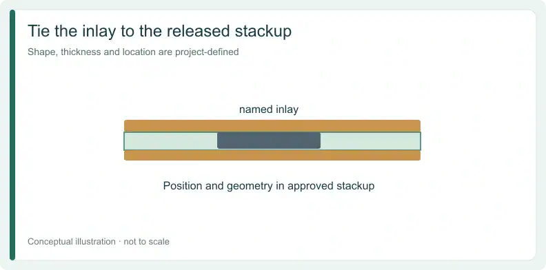
Give the insert its own identifier and connect it to the stackup revision. Show its outline and position relative to the features used to locate it. If a drawing leaves thickness or position open, a section returned later may be hard to compare with the intended construction.
Keep the electrical test object and the physical inlay description linked to the same revision. If geometry changes during feasibility review, record the new version and reopen the route confirmation. This article does not supply a dimensional allowance or a general tolerance.
Who owns the lamination route: buyer or fabricator?
The buyer controls the required material identity, geometry and approval of changes. The fabricator owns the integration route and must state in writing whether it applies to that exact combination. The buyer should not invent lamination temperatures or pressures and present them as a proven recipe.
A broad statement that a material is “PCB compatible” does not name a current grade, a specific inlay geometry or the route offered for that combination. The CPES research video describes lamination compatibility as part of a research prototype presentation; it does not supply a completed qualification for your order.
For the separate general question of mixed-material build evidence, see evaluating hybrid PCB lamination evidence before release. Keep generic lamination discussion separate from the supplier's written confirmation of this inlay.
For a conventional winding board without an embedded magnetic inlay, send the Gerber files with the stackup or fabrication drawing for a quote and free DFM review.
What integration evidence should come back from a pilot build?
Agree the pilot evidence before a feasibility build: an inlay section tied to the drawing revision, traceability to the material lot, and an electrical check before and after the relevant process exposure. These are suggested evidence fields, not a standard test plan or universal pass criteria. Each party must know who supplies and reviews them.
The 2021 AT&S presentation outlines a developer test sequence with electrical measurements at the start, after preconditioning and after stress, and marks that work as still to be continued. The sequence is an example of evidence to discuss, not permission to transplant its samples or conditions into another order. Agree the test object and criterion for your project instead.
| Field | Who supplies it | Known only when | If missing |
|---|---|---|---|
| Manufacturer, grade and family | Buyer and material source | Current datasheet and test conditions are identified | Hold |
| Preform shape, thickness and position | Buyer | Shown in the released stackup drawing | Hold |
| Integration route | Fabricator | Written confirmation names this material and geometry combination | Hold; unverified claim |
| Handling and exposure assumptions | Fabricator | Items requiring verification are listed, without invented settings | Hold |
| Pilot evidence to return | Both | Section at inlay, material-lot traceability and before/after electrical check agreed in advance | Hold |
| Change owner and approval | Both | Owner named; a grade or geometry change reopens the record | Hold |
| Long-term reliability | Project | Evidence is specific to the intended use | Unknown until supplied |
At RFQ, hold if the material identity, released geometry or named route is missing. A feasibility discussion may continue while those gaps are resolved, but the buyer should not commit the design to an inlay on the strength of an unnamed compatibility claim.
What do the cited sources not prove about reliability?
The cited developer presentation describes reliability work as ongoing rather than complete. The sources cited here do not establish long-term reliability for the proposed material and route in your product. Treat that item as unknown until the project receives relevant evidence and agrees how to evaluate it.
A prototype or assembled-module result can describe the reported test vehicle without qualifying a different bare-board inlay. The glued-plate study and the research-video module answer questions about their own constructions. They are not substitutes for traceability and a project-specific reliability record for a laminated insert.
Keep the difference clear between “not found in these reviewed sources” and “not offered by anyone.” The sources do not establish a current named offer here; they do not prove that no supplier has one. Ask for the actual material, route and scope rather than making either claim.
When should a buyer stop or move to a discrete magnetic core?
Hold the inlay decision when the manufacturer and grade, released geometry or fabricator-confirmed route is missing. Continue only as a feasibility discussion until the missing evidence is resolved. If the project cannot close those gaps in time, evaluate a conventional winding board with an external or planar core as a separate fallback.
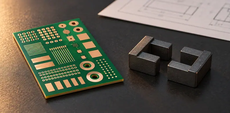
A fallback has its own interface and assembly decisions. The guide to defining a planar transformer winding stack and insulation addresses that separate design scope. It does not turn a bonded or external core into a laminated inlay.
Retain the open reliability item even when an inlay is feasible. A written route confirmation says what the supplier proposes for a named combination; it is not by itself a life test or an acceptance result. Agree the evidence for the use case before making that conclusion.
Frequently Asked Questions
Can I use published permeability tables to pick an inlay?
Not by themselves. The cited developer comparison gives nominal values for anonymous materials. Request current grade-specific data and conditions for the intended use.
Does “compatible with PCB lamination” in a research video mean the route is qualified?
No. A narrated claim without the named grade, applicable route and supporting section does not qualify the proposed order. Ask the fabricator for written confirmation and evidence.
Is a sample count from a developer reliability program a lot sampling plan?
No. A per-panel sample count in the cited presentation describes that developer’s program. The project must agree its own test object, sampling and acceptance basis.
Did the cited sources show finished long-term reliability?
The cited developer presentation lists reliability as ongoing. That record does not establish completed long-term reliability for your material and route.
If the project moves to the external- or planar-core fallback, send the conventional winding-board Gerber files and stackup or fabrication drawing for a quote and free DFM review. Add a BOM only if assembly is also required.
Upload your files today · Free DFM check before production · Ship worldwide
Get your PCB prototypes in as fast as 24 hours. We handle FR4, Rogers, and hybrid boards, with standard builds up to 24 layers and higher layer counts subject to engineering review — free prototypes for 2–4 layer FR-4 boards, no minimum order.
Just upload your Gerber + BOM — we source every part, assemble, and inspect (AOI + X‑Ray) so you don't have to chase suppliers. PCB assembly typically takes 5–8 working days once all components are in stock. The confirmed delivery schedule is subject to your quotation.