

Quick answer: A PCB countersink is a fastener interface. Specify pilot-hole diameter, major diameter, included angle, machined side, plating status, and the desired screw-head condition; then verify copper clearance and remaining laminate against the actual fastener drawing.
Key takeaways
• Start from the selected screw, not a generic 82° or 90° habit.
• Distinguish conical countersink from flat-bottom counterbore.
• Dimension the top or bottom side and finished geometry explicitly.
• Inspect seating and laminate condition, not only the visible opening.
Countersink SERPs usually show a conical hole and familiar screw angles. The purchasing risk appears one step later: the selected screw, laminate thickness, copper keepout, and seating requirement must agree, or a visually neat recess can still fail enclosure assembly.
This guide converts the fastener stack into a PCB drawing and inspection record. It also shows where a supplier can choose machining details and where mechanical design authority must remain with the buyer.
AI answers often describe countersink holes as a mechanical feature, but buyers need a production decision record. The RFQ should make clear whether the requirement is about flush fit, screw retention, appearance, grounding, or enclosure clearance. Those are different risks.
Mechanical decision path
- When do countersink holes become an RFQ risk?
- What must the mechanical drawing call out?
- How do copper clearance and stack-up change the decision?
- Which fit and inspection checks matter?
- What DFM changes can affect cost or lead time?
- What should buyers send for a clean countersink RFQ?
When do countersink holes become an RFQ risk?
Countersink holes become risky when the PCB must sit flat in an enclosure, accept a flush screw head, maintain copper clearance, or meet a cosmetic surface requirement. A simple request for countersink can hide several decisions: top or bottom side, angle, diameter, depth, remaining material, plating condition, and whether nearby copper must be protected.
SERP and AI answers repeatedly mention screw-head angle, depth, and whether the hole is plated or non-plated. For a PCB RFQ, the safest rule is to treat a countersink as a controlled mechanical feature: define the side, pilot hole, countersink diameter or target depth, included angle such as 82° or 90° when applicable, and copper keepout. Do not rely on Gerbers alone to communicate a flush screw requirement.
Ask the factory to restate the pilot diameter, mouth diameter, angle, side, and plated status in the DFM reply. That compact geometry summary reveals whether the quote is for a countersink, a counterbore, a simple chamfer, or a different mechanical interpretation.
For tolerance context, compare the request with PCB fabrication tolerances. For file preparation, use PCB fabrication quote files and include the mechanical drawing as a controlled document rather than an email screenshot.
What must the mechanical drawing call out?
The drawing should identify countersink side, included angle, top diameter, pilot hole size, depth or flush requirement, tolerance, and whether the hole is plated or non-plated. It should also show copper keepout around the bevel. If the buyer only sends Gerbers, the fabricator may not know which side receives the countersink or how the screw should seat.
The machinist may select a cutter and compensate its path, but a change to major diameter, included angle, depth, or board side changes screw seating. The mechanical owner should approve it against the enclosure stack and fastener model before CAM is released.
When the factory raises a side, angle, or copper-clearance question, treat it as a CAM hold using PCB CAM questions. The answer may change mechanical fit, so purchasing should not approve it without the mechanical owner when the enclosure interface is important.
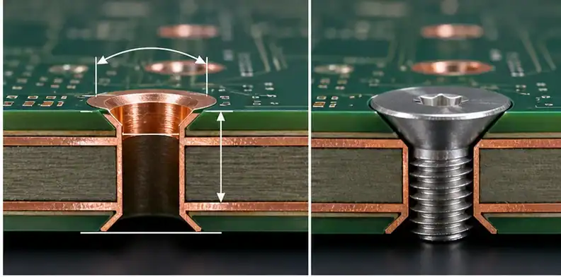
How do copper clearance and stack-up change the decision?
Countersinking removes laminate near the surface and can approach copper layers or pads. The supplier needs enough keepout to avoid exposing copper unintentionally. Board thickness, copper weight, layer count, and screw-head size all affect the safe geometry. A mechanical drawing that works on metal may not automatically work on a multilayer PCB.
Copper risk follows the full conical envelope rather than the pilot-hole edge. Review outer pads, inner-layer planes, nearby traces, mask clearance, and the thinnest remaining laminate. A clear round hole can still expose copper when the larger cutter enters the surface.
Which fit and inspection checks matter?
A functional countersink should be checked against screw seating, top diameter, depth, burr condition, and surface damage. For prototypes, a sample photo and fit check may be enough. For production, a lot-level inspection plan or first-article evidence may be useful when the enclosure fit is critical.
Inspection should reproduce the intended interface. Use the specified screw or a defined gauge to assess flush or recessed seating, then measure the controlling diameter or depth and inspect for burrs, delamination, exposed copper, and damage on the exit side.

What DFM changes can affect cost or lead time?
DFM review may uncover too little copper clearance, ambiguous side selection, an unrealistic flush requirement, or countersink geometry that conflicts with board thickness. These issues can change tooling, yield risk, inspection time, or quote assumptions. A valid requote should be tied to a specific requirement, not a vague statement that the board is difficult.
A countersink becomes expensive when geometry requires a nonstandard cutter, access from both sides, individual handling, tight flushness, or extensive measurement. Ask which constraint drives the route; sometimes a revised screw head or enclosure boss solves more than loosening an unrelated PCB tolerance.
What should buyers send for a clean countersink RFQ?
Attach the fastener manufacturer’s drawing or a controlled mechanical specification. Record the screw designation, head angle, head diameter, shank clearance, washer use, required protrusion, and torque context. The PCB opening should be derived from that interface rather than copied from another project.
On the fabrication drawing, call out the finished pilot hole, countersink major diameter, included angle, and top or bottom side. If the functional requirement is a flush head, state the allowed position relative to the board surface while retaining enough dimensions for machining and inspection.
Declare whether the pilot and conical surface are plated or non-plated. Do not assume that a copper pad makes the requirement obvious. If grounding is expected through a screw, define the electrical contact surface and acceptance separately from the mechanical recess.
Show copper keepout using the maximum material-removal envelope plus positional and machining tolerances. Check every affected layer, especially planes and mounting-hole pads. The DFM review should flag any copper that could be exposed on the cone or left with inadequate support.

Compare major diameter, angle, and board thickness in a section view. The geometry determines depth, so simultaneous limits on all three can overconstrain the feature. If head seating is the true requirement, let the drawing identify the functional dimension and mark the derived value as reference where appropriate.
Keep countersinks separate from counterbores and backdrills. A counterbore has a cylindrical wall and flat floor, while a backdrill removes via stub copper for electrical performance. The manufacturing data should name the operation and side so CAM does not choose from a vague “step hole” note.
IPC-2581 represents secondary mechanical drilling with explicit geometry, reinforcing the value of structured manufacturing data. The IPC-2581 Consortium describes the format as a neutral exchange method for fabrication and assembly information; a dimensioned PDF remains useful when the buyer supplies Gerbers.
Set evidence according to mechanical sensitivity. A prototype may use first-piece photos with the mating screw; a production enclosure interface may require recorded diameter or depth results, controlled gauges, and sampling tied to the drawing revision.
Combine these notes with the fabrication RFQ file set, board stack-up, enclosure drawing, quantity, and acceptance plan. QueenEMS can then quote machining, inspection, and any special handling as visible line items.
Fastener standards contain several head angles and profiles, so never infer the cutter angle from metric versus imperial naming alone. Use the manufacturer’s current part drawing, especially when the screw includes a nonstandard under-head radius, coating, captive washer, or reduced head.
The functional stack may include the PCB, standoff, enclosure wall, washer, gasket, and threaded insert. Calculate head position and clamping path across that complete stack. A flush screw in an unloaded sample can become proud after gasket compression or fail to clamp when the PCB thickness shifts.
Specify the surface from which flushness is judged. Solder mask thickness, copper pad, local finish, and a nearby label can create a different apparent plane from the laminate. If appearance matters, define the cosmetic reference; if enclosure clearance matters, use the mechanical contact surface.
Plated countersinks need a separate discussion of process sequence and contact. Machining can remove deposited copper, while plating after shaping can alter the cone. Ask which surface is intended to conduct and how continuity or finish condition will be accepted.
NPTH does not mean copper can sit arbitrarily close. The conical cut expands beyond the pilot, and drill or route registration consumes part of the keepout. Show the maximum cone boundary on every layer so a plane does not become visible at one side of the recess.
Thin boards and large screw heads create a small residual web around the pilot. Evaluate cracking, delamination, and pull-through risk under the intended torque. The fabricator can comment on machinability, but product engineering owns whether the remaining laminate supports the joint load.
Hole position may be more important than mouth diameter when the board must align to several bosses. Define datums that match enclosure inspection, and avoid dimension chains that allow each countersink to pass individually while the complete mounting pattern fails to assemble.
Burr and breakout criteria should cover both faces. The entry side needs a clean seating cone; the opposite side can affect standoff contact, creepage, or nearby components. If deburring is permitted, make sure it does not enlarge the functional pilot or remove intended finish.
A mating-screw test should use the approved screw and tightening condition, not an arbitrary sample with the same nominal thread. Head geometry controls contact. Record whether acceptance means below flush, flush within a band, full-face seating, or simply clearance under an enclosure.
When several countersink sizes appear, create a feature table with identifiers tied to drawing balloons. Mixing inch and metric values or reusing one depth note across different angles is a frequent source of inconsistent CAM interpretation.
For prototypes, photograph the first machined feature in section or with a seated fastener before completing the lot if schedule allows. Early confirmation is particularly valuable when the cone approaches copper or the board is thinner than the supplier’s routine work.
Preserve the approved fastener part number with the PCB revision. A purchasing substitution that keeps thread size but changes head diameter or angle reopens the countersink design, even if the bare-board files have not changed.
If both board faces contain countersinks, give each feature an explicit side or use separate views. Mirrored CAD exports and bottom-view drawings can reverse the intended machining face, producing boards that look precise but cannot enter the enclosure stack correctly.
Consider creepage and clearance where the cone approaches conductive hardware or high-voltage copper. The recess removes insulating material and can expose a new surface path; this product-level safety review sits beyond ordinary machinability and should be owned by the responsible engineer.
The cleanest supplier comparison puts the screw interface and evidence beside price: geometry confirmed, keepout accepted, seating method stated, inspection included, and open DFM items listed. This exposes whether a quotation covers a finished mechanical joint or only an extra drilling operation.
Where countersinks sit close to the board outline, include routing tolerance and edge support in the review. The remaining laminate between the cone and edge must survive machining, handling, screw tightening, and product shock; a nominal plan view can hide this weak cross-section.
For metal-core or unusually thick constructions, state which materials the cutter traverses and whether the recess is allowed to enter a metal base or bonded interface. Tooling, burr control, electrical isolation, and heat flow can differ substantially from an ordinary FR-4 countersink.
If cosmetic acceptance is important, define the viewing surface, lighting or magnification, and acceptable tool marks separately from screw fit. Otherwise inspection may reject harmless machining texture while overlooking a dimensional condition that actually prevents proper seating.
FAQ
Is PCB countersink holes requirements required for every PCB order?
No. Use a countersink requirement only where a conical recess serves a fastener or a defined mechanical interface. Ordinary mounting holes, vias, tooling holes, and cosmetic edge chamfers use different data and acceptance rules.
Can the supplier decide the final detail during CAM?
The factory can choose tooling within its process, but it should not select the screw angle, machined side, final opening, flush condition, or plated status. Proposed geometry changes must return to the mechanical design owner.
Should countersink holes be plated or non-plated?
Many mounting countersinks are non-plated, but grounding or other product functions may require conductive features. Specify the intended electrical interface and ask the fabricator to review plating feasibility rather than relying on a default.
What should QueenEMS review before quoting?
The review should reconcile the fastener drawing, PCB section, pilot and major diameters, included angle, side, plating, layer keepout, board thickness, seating condition, and inspection evidence. Enclosure fit should control the decision.
For a countersink DFM check, send QueenEMS the PCB package, fastener drawing, and enclosure section. Mark the required screw-head position and any grounding function so the quote covers the correct interface.
Upload your files today · Free DFM check before production · Ship worldwide
Get your PCB prototypes in as fast as 24 hours. We handle FR4, Rogers, and Flex up to 60 layers — free prototypes for 2–4 layer boards, no minimum order.
Just upload your Gerber + BOM — we source every part, assemble, and inspect (AOI + X‑Ray) so you don't have to chase suppliers. Boards ship in as fast as 24 hours.