
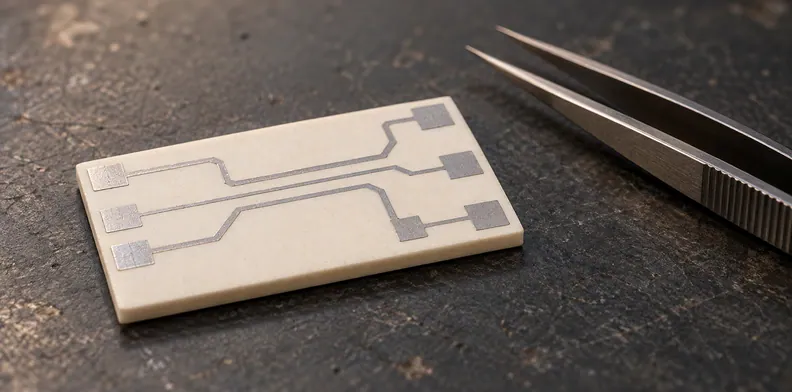
Quick Answer: A thick-film silver conductor’s leach-resistance entry describes the ceramic specimen, solder, temperature and exposure used in the maker’s test; it is not a rating for your assembly process. Compare those conditions with the actual joint and keep missing fields unknown. The assembly owner sets the evidence and acceptance criteria for the termination after attachment.
A ceramic circuit may arrive with a named silver-containing conductor and a material sheet that reports thick film silver solder leaching data as a dip count. Before releasing it for assembly, the buyer needs to know what that result describes and whether it covers the intended solder exposure. A number without its specimen and test conditions cannot answer that question.
What does a thick-film leach-resistance figure actually report?
A leach-resistance figure reports the result for the maker’s specimen under the stated test conditions. It is not an allowable number of soldering operations for a different circuit. To interpret it, keep the conductor identity, substrate, solder, exposure and the maker’s stated status of the values together.
The DuPont 7484 technical data sheet, marked MCM7484 (10/2014), is a historical example for a palladium/silver conductor. It reports typical laboratory values in separate columns for alumina and a named dielectric surface. The document does not establish current availability or a QueenEMS material offering.
For the leach entry, the sheet specifies the solder, temperature, dip duration and line geometry. It does not state the flux or define the endpoint that ends the dip count. The maker describes the values as typical laboratory data, rather than product specifications. Ask for current documentation and the missing test details before using the entry in an order decision.
If you are still selecting the metal system itself, see choosing between printed and deposited ceramic film systems. The decision here starts once the design names a conductor.
Which details must match before a data sheet applies to your build?
Compare the exact conductor, underlying surface, specimen, solder and exposure with the intended assembly, using the current maker document. Mark each difference and missing field rather than treating a shared material name as a match. The responsible engineer decides whether the historical test is relevant and what additional evidence is needed.
This worksheet shows how to read one historical sheet. The project team completes the “Your assembly” column; the worksheet assumes no match or release.
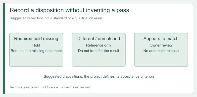
Suggested dispositions: Hold, a required document or field is missing; Reference only, the sheet’s condition differs from or cannot be matched to the build; Owner review, the condition appears to match, but the owner still decides whether the test is relevant evidence.
Matching the 7484 leach entry to your solder process
| Evidence field | 7484 sheet statement | Your assembly | Match (enter: same / different / not stated) | Suggested disposition |
|---|---|---|---|---|
| Conductor and document | Palladium/silver; MCM7484, 10/2014; ratio not stated | Enter exact code and current document | — | Hold if missing; otherwise Owner review |
| Underlying surface | Alumina and DuPont 5704 dielectric columns; properties based on 96% alumina substrates | Enter substrate and conductor surface | — | Reference only if different or unmatched; otherwise Owner review |
| Firing history | Footnote lists one, three or five firings on a 30 or 60 minute profile; the history behind each value is not identified | Enter recorded history | — | Hold until the maker identifies it |
| Leach specimen | 500 µm lines | Enter actual feature and joint | — | Reference only if different or unmatched; otherwise Owner review |
| Solder and temperature | 62Sn/36Pb/2Ag at 230 °C | Enter actual alloy and measured conductor temperature | — | Reference only if different or unmatched; otherwise Owner review |
| Exposure per dip | 10 seconds | Enter method and molten contact history | — | Reference only if different or unmatched; otherwise Owner review |
| Flux and endpoint | Not stated for the leach test | Enter process and criterion | Not stated | Hold |
| Reported leach result | 7–9 dips, typical laboratory value | Enter project evidence and owner criterion | — | Owner review |
| Other solder property | Separate solder-acceptance test on pads under different conditions | Enter the requirement, if any | — | Reference only for the leach question; do not merge the histories |
What the comparison leaves open
Even when several fields appear to match, the sheet leaves the leach endpoint and flux open. Ask the maker for those details and the current document. A complete comparison identifies the remaining uncertainty; the responsible engineer still decides what evidence supports release.
Why is a solder dip test not the same exposure as your assembly?
The cited material test counts dips under one stated solder and temperature condition. A circuit assembled by another method can see a different contact history at the conductor. Record the actual alloy, measured temperature at the feature, molten contact time, assembly sequence and any rework before comparing it with the sheet.
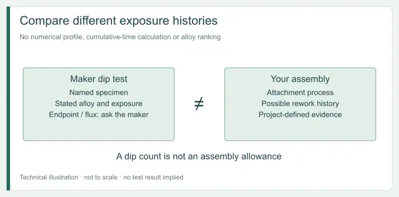
Do not convert the sheet’s dip count into a permitted total contact time. The document does not provide the missing endpoint, and its typical result belongs to the reported test. Nor does it establish how a different alloy or a different feature size would behave.
If rework is possible, include it in the process record sent for review. A first-pass assembly condition and a later rework condition are separate histories. The owner should decide whether existing evidence covers both rather than assuming that one test entry answers every exposure question.
What does the ceramic monoblock note show, and what can’t it prove?
CTS describes tin interacting with fired silver on the terminations of its own ceramic monoblock filters, with heat and dwell affecting that interaction. It also describes a difference between edge and center metallization on those components. That is a component example, not qualification of a printed conductor on your ceramic substrate.
The historical CTS AN1016 technical brief concerns a defined filter termination and its application. Its process advice and numerical examples belong to that product context. The useful comparison is the need to know the actual object, location and process history behind a report.
How should termination condition be checked after attachment?
The assembly owner should define which joints and conductor locations need evidence after the actual attachment process, along with the method, sample scope and criterion. Link each record to the conductor and substrate lot and its thermal history. An intact-looking surface alone does not establish qualification or identify a failure cause.
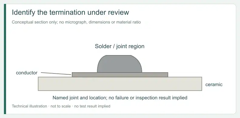
When a supplier offers a report, ask which location it assessed and whether that location went through the same process sequence as the product. An image of one feature is evidence about that feature under the stated method; it should not silently stand in for every joint on the circuit.
If the observation is unclear or differs from the accepted record, retain the result and refer it to the responsible engineer. The project decides what further investigation is appropriate. No particular inspection method, sample count or pass limit follows automatically from the two historical documents.
Wire bonding or sinter attachment involves another interface decision. The guide to specifying finishes by bonding or sintering interface addresses those surfaces separately from solder exposure of a fired conductor.
Which evidence is a vendor observation and which is your own result?
Separate a material maker’s test from an assembly trial on the actual circuit, and reopen the comparison when a relevant process changes. The maker’s result provides a stated reference; the project result addresses its own specimen and conditions. The acceptance owner decides whether either record is sufficient for release.
| Evidence item | Generated by | What it tested | Basis | Suggested disposition |
|---|---|---|---|---|
| 7484 material-sheet leach entry | Material maker | Reported lines and dip conditions; endpoint and flux not stated | Historical maker test result | Reference only |
| Maker product specification for 7484 | Material maker, on request | Specification terms not shown in the typical-property sheet | Maker specification, if obtained | Owner compares it with the build; it is not assembly evidence |
| Assembly-specific result | Assembler or buyer trial | Named circuit and recorded solder history | Project test result | Owner evaluates against project criterion |
| No evidence on the intended joint | Not yet generated | Unknown | Suggested buyer check | Owner records either a trial or a documented decision that existing evidence suffices |
| Alloy, profile, rework or conductor change | Proposed by supplier or buyer | Prior result may describe a different build | Suggested buyer change control | Re-review before release |
On the 7484 sheet, the solder-acceptance and leach entries are separate tests, so neither row supplies inputs for the other.
What should go to the supplier before the ceramic order is released?
Provide the named conductor and current maker-document revision, the intended solder process, the joints under review and the acceptance owner. Tie each unresolved field to a disposition in the evidence map. A supplier response can then identify what remains reference-only, what needs an assembly trial and what must return to engineering.
The 7484 sheet says its product specifications are available on request; ask for the current specification alongside the leach-test endpoint and flux, and record which questions remain open.
When the process or material changes, retain the earlier record rather than silently replacing its conditions. The owner can compare the proposed build with the prior evidence and decide whether that evidence still applies. A quote discussion does not itself qualify the termination.
Frequently Asked Questions
Does a solder-leach dip count tell me whether the conductor survives my reflow?
No. A dip count describes the maker’s own test conditions and cannot be used as a reflow limit for a different assembly.
Can a ceramic filter’s soldering guidance qualify my ceramic circuit?
No. The CTS example concerns a component termination. It is an analogy, not acceptance evidence for a printed substrate conductor.
Does silver-bearing solder settle the leaching question?
No. The historical sources describe their own test or product contexts; they do not establish the alloy choice or qualification for your circuit.
If the termination looks intact, is the joint qualified?
Appearance alone does not establish acceptance. The assembly owner defines the evidence and criterion for the actual joint.
Send your released files for a quote and free DFM review.
Send the ceramic substrate drawing, conductor system and soldering requirements for review. Identify the material evidence needed for the order.
If assembly is required, identify the fitted parts, solder system and customer-supplied items. Confirm the substrate and assembly scope before ordering.