
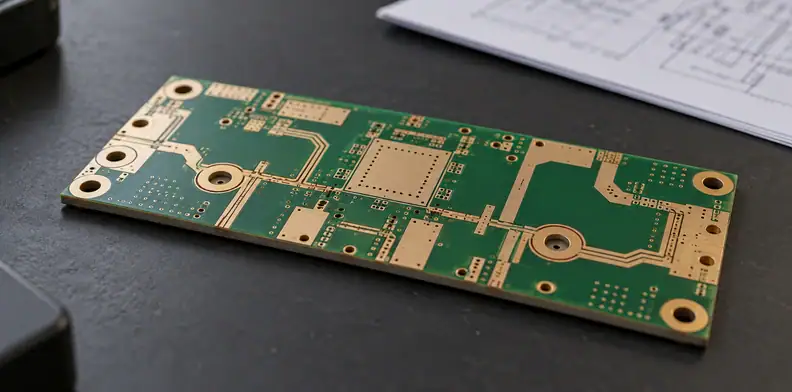
Quick Answer: Read non-magnetic PCB evidence by its measured quantity, reference and specimen, rather than accepting the label alone. A published copper-free substrate result does not establish the properties of a finished RF board with its specified conductors, finish and coatings. Keep every uncovered construction detail open for the instrument or design owner to resolve before release.
A buyer may receive a susceptibility table with a supplier's drawing and a short note saying the board is non-magnetic. The useful question is what that evidence establishes for the part being ordered. Non-magnetic PCB evidence needs enough context to distinguish a material observation from a result on the delivered board.
The example here comes from a 2014 accepted-author manuscript. Its quantities, specimen preparation and limitations are useful reading lessons. They do not provide a current laminate recommendation or a finished-board acceptance limit.
What should non-magnetic PCB evidence establish first?
The instrument owner must define the property, reference and tolerance that the evidence needs to address. In the cited magnetic-resonance study, the concern was field distortion associated with a material's susceptibility difference from water. A description such as diamagnetic therefore does not, by itself, answer whether a board meets an instrument requirement.
Wapler and colleagues reported that, to their knowledge, all their tested materials were diamagnetic. They nevertheless judged glass-fibre laminates particularly unsuitable for their MR context. These statements address different things: the sign of the material response and its difference from the reference. Neither supplies a universal pass value for an RF PCB order.
Which susceptibility quantity is the report stating?
Check the column heading before interpreting a sign or comparing values. One table row may contain susceptibility relative to water, density, and density-normalized absolute susceptibility. Those are different quantities. A positive value relative to water does not establish a positive absolute susceptibility, and a density-normalized entry cannot replace an unnormalized one.
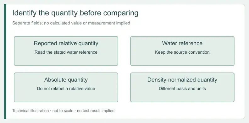
In Table 1 of the Wapler et al. accepted-author manuscript, the Bungard FR4 entry is 5.29(2) ppm relative to water. Its density is 1.952(2) g/cm³. The rightmost entry, −1.918(9), is absolute susceptibility in ppm divided by density in g/cm³, not absolute volume susceptibility. Section 2.3 takes water's susceptibility at 20°C as −9.032 ppm when converting relative values to absolute ones, before dividing by density.
This is arXiv v2, not a verified copy of the publisher's final table. Journal DOI: 10.1016/j.jmr.2014.02.005.
Quantity and reference reading key
S = source definition, with reference. E = editorial reading aid.
| Reported item | Source meaning | Reading disposition |
|---|---|---|
| S, Table 1: χ − χH₂O | S, Table 1: difference from water, in ppm | E: retain the reference; sign alone is insufficient |
| S, Table 1: ρ | S, Table 1: density in g/cm³ | E: do not read it as susceptibility |
| S, Table 1: rightmost column | S, §2.3: absolute susceptibility normalized by density | E: compare only on the same normalization basis |
| S, Table 1 caption: parentheses | S, caption: uncertainty in the final digit or digits | E: also read the PCB-specific caution in §3.1 |
| E: absolute volume susceptibility | E: no separate FR4 value printed in Table 1 | E: any derivation needs its reference basis; no conversion result is supplied here |
How should buyers read the stated PCB uncertainty?
Read the parenthesized uncertainty together with the authors' stated exclusions and cautions. Section 3.1 warns that realistic PCB and fibreglass uncertainties are probably larger than the displayed figures because field-map geometry can be distorted. Do not assign the authors' smaller, temperature-limited uncertainty near water to the FR4 row.
Their broader interpretation also needs its qualification. In section 5.1, the authors suggest some generality across manufacturers based on the variation observed in glasses and polymers. Section 2 explains that the authors excluded composition variation from the uncertainty figure and checked sources or batches for only some materials. Table 1 identifies one FR4 entry, from Bungard. That combination does not document the grade or lot of a proposed RF laminate.
Which specimen did the published FR4 result cover?
The reported specimen was Bungard FR4 without a copper layer and with fibres orthogonal to B0, according to Table 1's footnotes. The experiment used a 9.4 T field and a temperature range of 20 ± 2°C. These details identify the study's evidence; they are not conditions prescribed for testing your board.
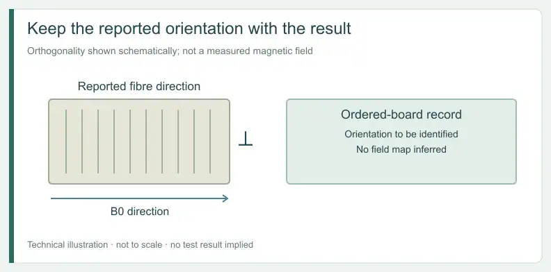
The source does not separately report that FR4 specimen's dimensions. Its standard sample dimensions must not be relabelled as the FR4 dimensions. For glass and PCB samples, section 2.1 says the glue-layer thickness was not visible in a cut through the stack; the authors concluded the glue layers were negligible. This describes their preparation, not the bonding materials in a production PCB.
What does a copper-free result leave unproven?
It leaves the delivered conductor-bearing construction outside the demonstrated specimen scope. The specimen was reported without a copper layer. Plated holes, surface finish, mask and legend are not reported in the source as construction details of that FR4 specimen. Their evidence gaps do not establish either acceptable or unacceptable magnetic behaviour for a finished board.
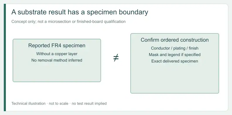
Section 5.1 states that the study measured only non-conductive materials. It notes that induced eddy currents in conductive samples could cause heating and vibration and may limit the measurement method. Extending the result to a copper-bearing board therefore needs more than attaching the substrate table to an order.
Use the separate guide to recording finish type and thickness evidence when identifying that part of the construction. Finish evidence remains a separate record that this study did not report. No magnetic behaviour follows from the finish name or its thickness report here.
How do you map the specimen to the delivered board?
Compare the source specimen with the released construction element by element, keeping the source wording intact. Record the actual drawing identity beside it, then state whether that evidence covers the decision. An empty project entry remains unresolved. Assign an owner who can supply the missing identity or decide what further evidence is necessary.
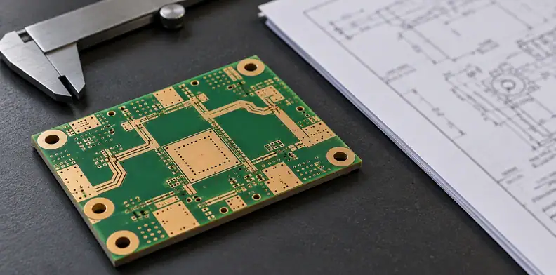
Specimen-to-delivered coverage record
The following is a suggested buyer reading aid, not a test, sampling or qualification method. S = source statement, with reference. E = editorial entry or disposition; all Owner cells are E.
| Element (E) | Source record | Delivered record (E) | Coverage (E) | Disposition (E) | Owner (E) |
|---|---|---|---|---|---|
| Substrate identity | E: Bungard FR4 (Table 1); grade/lot not reported in source | Enter grade and lot | Identity unresolved | Request matching identity evidence | Design owner / material supplier |
| Conductor and plating | E: without copper layer (Table 1 fn b); plating not reported in source | Enter conductor construction | Not covered by this evidence | Request appropriate evidence | Instrument owner / measurement provider |
| Plated holes | E: not reported in source | Enter hole construction | Not covered by this evidence | Resolve scope | Design owner |
| Surface finish | E: not reported in source | Enter finish record | Not covered by this evidence | Resolve scope | Design owner |
| Mask and legend | E: not reported in source | Enter specified materials | Not covered by this evidence | Resolve scope | Design owner |
| Fibre orientation | S, Table 1 fn a: orthogonal to B0 | Enter delivered orientation | Applicability unresolved | Document applicability | Instrument owner |
| Specimen form | E: FR4 dimensions not reported in source | Enter board geometry | Geometry unresolved | Do not assume a match | Instrument owner |
| Field and temperature | S, §§2, 5.1: 9.4 T; 20 ± 2°C | Enter required conditions | Applicability unresolved | Resolve applicability | Instrument owner / measurement provider |
| Uncertainty | S, §3.1: PCB uncertainty probably larger | Enter required evidence basis | Read with caution | Retain exclusions | Measurement provider / design owner |
| Source version | S, p.1: 2014 accepted-author manuscript | Enter controlled reference | Version identified | Keep version with record | Design owner |
Who resolves evidence gaps before the board is released?
The instrument or design owner resolves whether the evidence is sufficient for the intended decision. That may mean requesting specimen-matched evidence from a measurement provider, documenting an accepted limitation, or recording why an item is outside scope. The fabricator confirms the as-built construction identity; that confirmation alone does not establish magnetic properties.
Keep the decision with the drawing revision and the evidence it actually uses. If a material, finish or construction changes, the responsible owner should revisit the affected scope rather than carrying an earlier conclusion onto a different board.
Frequently Asked Questions
Does negative susceptibility mean a board is acceptable?
No. The sign does not describe the whole acceptance decision. In this study, diamagnetic materials could still differ substantially from the water reference. The instrument owner must define the relevant property, comparison and criterion.
Can the published FR4 value stand in for my RF laminate?
No. Table 1 identifies a copper-free Bungard specimen. It does not identify your laminate grade or lot, finish, coatings or completed geometry. Those gaps need an explicit project disposition.
Does the 9.4 T field restrict every use of the data?
The authors believed their diamagnetic results also applied at other fields. That is their stated interpretation. It does not qualify another construction or define how a finished conductive board should be measured.
Does this source set a standard PCB pass value?
No. It is a material study with specified methods and limitations, not a finished-board acceptance standard. Its values must not become an order's pass threshold without a separate, justified project requirement.
Send your released files for a quote and free DFM review.
Send Gerber, stackup and the released material list for review. Identify parts and finishes subject to nonmagnetic requirements and required evidence.
For assembly, identify the components and finishes subject to nonmagnetic requirements. Add the BOM and agree who supplies the required evidence.