
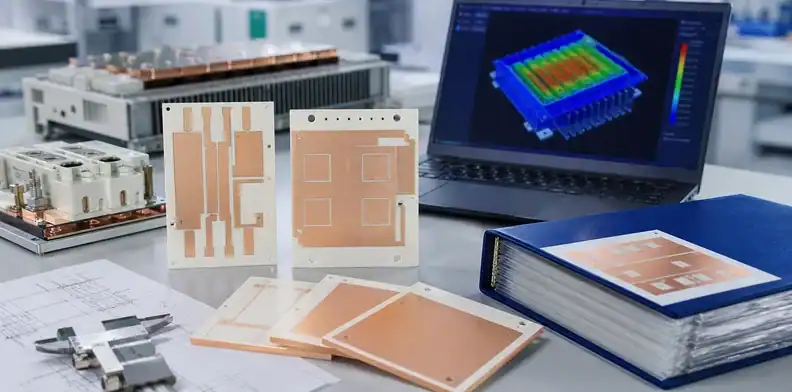
Quick Answer: Selecting a ceramic substrate for an IGBT or SiC module starts with the module’s electrical, thermal and mechanical loads. Alumina DBC may meet a cost-sensitive design, AlN DBC may help reduce the ceramic layer’s thermal resistance, and Si3N4 AMB merits evaluation where thermal cycling and mechanical durability are demanding. Compare the actual constructions, including ceramic grade, copper geometry, bonding route, insulation requirements, finish, attachment process and qualification evidence. Material names alone cannot establish the module’s reliability.
Key takeaways
- IGBT and SiC modules usually need power-substrate thinking, not ordinary ceramic PCB purchasing.
- DBC, AMB, AlN, alumina, and Si3N4 are not interchangeable labels; each changes reliability, cost, and evidence.
- The buyer should ask for copper, ceramic, isolation, thermal, warpage, and production records before approving a route.
- QueenEMS can help overseas buyers turn early module substrate requirements into an RFQ package before large-scale supplier qualification.
An IGBT or SiC power-module substrate may face concentrated die losses, high current and repeated temperature excursions. The severity depends on the operating profile and package, so the device label alone does not rank its stress above every LED or sensor assembly. The substrate must carry current, conduct heat, provide insulation and tolerate the specified assembly and service exposures.
The Si3N4 selection discussion and AMB versus DBC comparison help narrow candidate constructions. A module RFQ then needs to connect that construction to the actual loss distribution, cooler, insulation barriers and tested assembly.
Table of Contents
- What does a ceramic PCB do inside an IGBT or SiC power module?
- Which substrate route fits the power-module load?
- When does AlN matter more than alumina?
- When should Si3N4 AMB enter the shortlist?
- What copper and isolation details belong in the RFQ?
- How should assembly and thermal cycling affect supplier choice?
- What evidence should buyers request before qualification?
What does a ceramic PCB do inside an IGBT or SiC power module?
In an IGBT or SiC power module, the ceramic substrate is both an electrical circuit carrier and a thermal path. It must connect power devices, isolate high voltage from the baseplate or heat sink, and move heat away from the die. That combination makes the substrate a reliability part, not only a printed circuit.
The practical sourcing problem is that buyers use several names for similar-looking parts: ceramic PCB, ceramic substrate, DBC substrate, AMB substrate, AlN substrate, Si3N4 substrate, and power electronic substrate. Those terms overlap, but they do not always describe the same manufacturing route. A normal ceramic PCB supplier may not be ready for a module substrate that needs thick copper, strong isolation, low void expectations, thermal cycling evidence, or customer qualification records.
For a new project, the buyer should start by naming the module load. Is the design a low- or medium-power industrial module, a high-current inverter, a traction or renewable-energy module, or an engineering sample for a SiC switch? The answer controls whether the RFQ can stay in a simpler ceramic PCB route or must move toward DBC or AMB substrate specialists.
Which substrate route fits the power-module load?
The first decision is not “which supplier is cheapest?” It is which substrate route matches the power density, voltage, reliability target, and production stage. DBC, sometimes written as DCB by suppliers, and AMB are common power-module substrate families, but the correct route depends on the module requirement.
The Ceramic PCB Guide maps the material and metallization routes; for a power module, the selection still has to follow the declared voltage, heat flux, isolation, and thermal-cycle load.
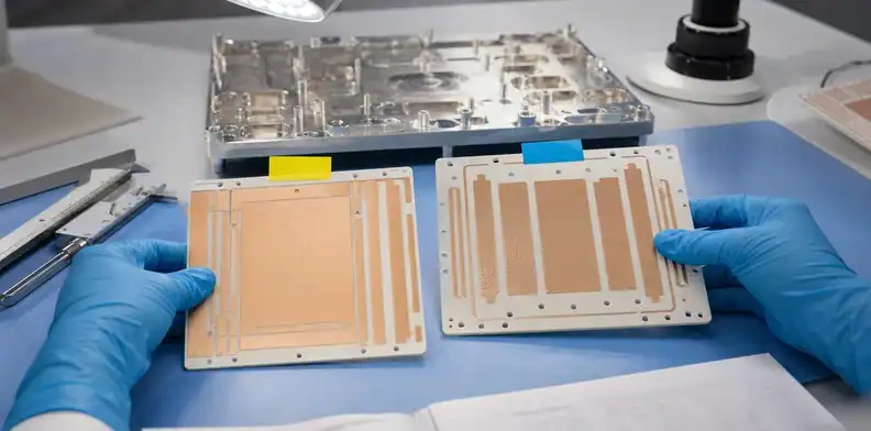
DBC substrates bond copper to ceramic and are widely used in power electronics. Alumina DBC may be considered where cost and mature supply matter and the reliability target is moderate. AlN DBC may be reviewed when heat spreading needs to improve while staying in a DBC-style route. AMB substrates use active brazing to bond copper to ceramic materials such as AlN or Si3N4, and they are often reviewed for higher reliability or harsher thermal cycling.
| Module situation | Route to discuss first | Main buyer question |
|---|---|---|
| Cost-sensitive industrial power module | Alumina DBC | Is thermal and isolation margin enough? |
| Higher heat flux module | AlN DBC or AlN AMB | Does the thermal path justify the cost? |
| SiC module with harsh cycling | Si3N4 AMB | Does mechanical reliability drive the route? |
| Early engineering sample | Prototype ceramic substrate route | What evidence is missing before qualification? |
| Customer qualification lot | Production DBC/AMB supplier | Which records must repeat lot to lot? |
The QueenEMS ceramic PCB manufacturer hub provides the broader fabrication context. For this module decision, name the intended substrate route before suppliers quote.
When does AlN matter more than alumina?
AlN matters when the module’s thermal path is the bottleneck and alumina no longer gives enough heat-spreading margin. Alumina remains useful because it is common, mature, and cost-effective. AlN becomes attractive when thermal conductivity, device temperature, package size, or heat sink interface drives the design.
A buyer should not choose AlN only because SiC or IGBT appears in the project name. Some modules can meet their thermal and reliability target with alumina DBC. Others need AlN because the device loss, switching condition, layout density, or cooling structure leaves less margin. The engineering owner should define what thermal condition forces the material change.
Before comparing substrates, mark each power die on a loss map. Record the conduction and switching losses used for each operating condition, the die footprint and the distance to neighbouring heat sources. A board-average power density can hide one heavily loaded switch. If the thermal simulation assumes all devices dissipate equally, confirm that this represents the relevant operating case rather than averaging away a local limit.
Keep the temperature reference attached to the model. A junction-to-case resistance taken from a complete module may already include the ceramic and its internal attachment. Adding the ceramic term again would count the same heat path twice. Conversely, a bare-layer calculation omits the die attachment, spreading and cooling interface. The module designer should reconcile those boundaries before attributing a temperature reduction to an AlN or Si3N4 substitution.
A useful supplier comparison therefore combines the proposed substrate drawing with that loss map and the cooler boundary. Request a revised thermal result when the copper pattern, ceramic thickness or mounting surface changes. This provides a direct reason for accepting or rejecting a material alternative, while the qualification plan separately evaluates the interfaces and cycling mechanisms that a steady-state thermal result cannot establish.
The RFQ should ask suppliers to state the AlN grade, conductivity basis, ceramic and copper dimensions, finish, flatness, and whether the material assumption is tied to the prototype result. If the supplier quotes AlN but does not explain how the route differs from alumina, the buyer has not received a production-ready answer.
For SiC designs, higher switching speed, compact layout, and local heat flux can increase pressure on the substrate and package. That does not automatically choose AlN; it means the substrate review should focus on the real heat path, die-attach exposure, cooling structure, and reliability target instead of treating the device name as the material decision.
When should Si3N4 AMB enter the shortlist?
Si3N4 AMB should enter the shortlist when mechanical reliability and thermal cycling are central to the module risk. Si3N4 is often discussed for power modules because its strength and fracture toughness can be useful where ceramic cracking, copper stress, or harsh cycling are major concerns.
This does not mean Si3N4 AMB is always the best choice. It can be more specialized, and the supplier pool may be narrower. The buyer should treat it as an engineering route, not a purchasing upgrade. Ask why the application needs it: traction inverter cycling, SiC module reliability, high current density, customer qualification, or a known failure mode in a previous DBC route.
For AMB, identify the offered ceramic, braze system, copper geometry, finish and flatness condition. The Rogers curamik product data, ©2026, provides concrete DBC and AMB constructions. Those supplier options establish that material and bonding route are separate decisions; their existence does not qualify another factory or an untested module.
What copper and isolation details belong in the RFQ?
The RFQ should define copper and isolation requirements before suppliers quote. In power modules, copper thickness affects current path, heat spreading, etching limits, bond stress, and cost. Isolation requirements affect ceramic thickness, spacing, test method, and customer acceptance.
Do not send only Gerber files and ask for “ceramic PCB for IGBT.” Add a substrate drawing or notes that state copper thickness target, ceramic family, finished thickness, creepage or clearance needs, voltage isolation requirement, surface finish, die-attach interface, and any backside copper or baseplate attachment assumption. If those items are unknown, ask suppliers to quote controlled options rather than guessing.
| RFQ field | Why it matters for modules |
|---|---|
| Copper thickness | Controls current, heat spreading, etching, and stress |
| Ceramic thickness | Affects isolation, thermal path, and mechanical behavior |
| Surface finish | Affects die attach, soldering, wire bonding, or assembly path |
| Isolation test | Creates receiving and customer release evidence |
| Warpage or flatness | Affects module attach and thermal interface |
| Copper balance | Affects substrate stress and repeatability |
Rogers’ curamik technical content notes that ceramic grade, ceramic thickness, and copper thickness influence isolation voltage, output power, and reliability in DBC/AMB substrate selection. That is the practical RFQ translation: copper and ceramic are not commodity line items.
How should assembly and thermal cycling affect supplier choice?
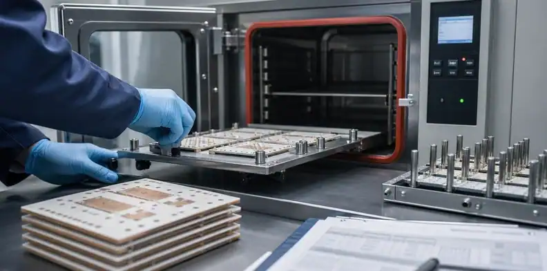
Assembly and thermal cycling should be part of supplier selection because the substrate may pass bare-board inspection and still fail during module build or reliability testing. IGBT and SiC modules can expose ceramic substrates to soldering, sintering, wire bonding, baseplate attach, encapsulation, thermal interface pressure, and repeated temperature swings.
Ask the supplier where its responsibility ends. A ceramic substrate supplier may ship a bare DBC or AMB substrate. A module assembler may own die attach, wire bonding, encapsulation, or final test. A PCB/PCBA partner may coordinate early samples but not own power-module qualification. The RFQ should separate these roles before a schedule is promised.
Match the damaged interface to the specimen
ECPE AQG 324, Release 04.1/2025, separates environmental exposure and module lifetime testing. A chamber temperature cycle changes the surrounding temperature; active power cycling produces temperature excursions through semiconductor losses and cooling. Equal cycle counts from those procedures are not equivalent endurance measurements. The relevant specimen must contain the interface being assessed.
| Observed issue | Useful evidence | Specimen needed |
|---|---|---|
| Ceramic crack near a copper edge | Mapped optical examination, targeted section and relevant thermal exposure | Representative metallized substrate; assembled witnesses if mounting adds load |
| Die-attach degradation | Thermal/electrical change, suitable interface imaging and confirmation of the suspected layer | Die attached with the production material and process |
| Wire or terminal interconnect fatigue | Electrical monitoring and examination of the affected connection | Module containing those interconnections |
| Cooler or baseplate attachment damage | Attachment inspection plus thermal response under the stated boundary | Mounted construction with the intended interface and restraints |
The table proposes investigation routes, not mandatory test settings. Confirm the visibility or measurement response of the suspected defect at the relevant interface before using that method for acceptance. A bare-substrate report cannot establish wire-bond lifetime, and a complete module failure cannot be assigned to ceramic without locating the damage. Keep lot, stack revision, sensors, waveform or chamber profile, inspection limits and individual outcomes attached to the result.
A module can pass a bare-substrate chamber test and later show rising thermal resistance during powered operation. Treat that as an illustrative investigation, not proof that the selected ceramic is unsuitable. First confirm comparable temperature sensing, electrical loading and cooler conditions, then locate which attachment or interconnection has changed. A thermal trend alone does not identify the damaged layer.
Compare the stressed specimen with its starting measurements and construction record. Select interface imaging or targeted sectioning for the suspected layer, preserving undamaged reference regions where useful. If the evidence points to die attachment, investigate that material and process before replacing the ceramic; if it locates a copper-edge crack, review the substrate geometry and its mounting loads instead. Neither branch follows solely from the label IGBT or SiC.
Verify a proposed correction on specimens containing the affected interface, with the relevant thermal or powered exposure and agreed inspection criteria. Keep specimens with different failure mechanisms distinguishable in the analysis. Passing an earlier test on an unassembled substrate cannot close a newly identified module-level mechanism, and changing to a more expensive ceramic does not remove the need to demonstrate the corrected construction.
What evidence should buyers request before qualification?
Before qualification, the buyer should request evidence that proves the selected route can repeat. The evidence does not need to be identical for every module, but the record should cover material, copper, isolation, inspection, assembly exposure, and change control.
At a minimum, ask for the approved drawing revision, ceramic family, copper thickness, bonding route, surface finish, inspection criteria, and any lot record that will ship with production parts. For high-reliability programs, add thermal cycling or power cycling expectations, customer documentation requirements, supplier quality scope, and the approval rule for material or process substitution.
| Evidence to request | Buyer purpose |
|---|---|
| Material and process statement | Confirms alumina, AlN, Si3N4, DBC, or AMB route |
| Dimensional and visual inspection | Supports receiving review |
| Isolation or electrical test | Confirms insulation requirement is checked |
| Finish confirmation | Supports die attach, soldering, or wire-bonding plan |
| Warpage or flatness data | Protects module assembly interface |
| Change-control note | Prevents silent material or route substitution |
This evidence-first approach also protects small buyers. If the project is still a prototype, the buyer can ask QueenEMS to help clean the RFQ package and identify which evidence is missing before moving to a specialist DBC or AMB supplier.
FAQ
Is ceramic PCB the same as DBC for IGBT modules?
No. DBC is a specific copper-on-ceramic power substrate route. “Ceramic PCB” is a broader phrase and may describe alumina, AlN, DPC, thick film, DBC, AMB, or other ceramic circuit structures.
Is AlN always better than alumina for SiC power modules?
No. AlN may improve the thermal path, but alumina can still fit some cost-sensitive or lower-stress modules. Engineering should define the heat path and reliability target before changing material.
When should a buyer choose AMB instead of DBC?
Review an AMB construction when its ceramic, copper pattern and bonding system may address the observed module failure mechanism. Compare that complete stack with the proposed DBC alternative under relevant conditions; the acronym alone does not prove greater strength or longer life.
What should I ask a ceramic substrate supplier for an IGBT RFQ?
Ask for ceramic family, copper thickness, bonding route, surface finish, isolation test, flatness or warpage assumption, inspection records, assembly boundary, and change-control rules.
Can QueenEMS build every IGBT or SiC module substrate?
No supplier should be selected that way. QueenEMS can help review prototype and small-batch RFQ files, clarify ceramic material and process assumptions, and identify when the project needs a specialist DBC or AMB production substrate route.
Send QueenEMS an IGBT or SiC ceramic substrate RFQ
Send the module application, device-loss information, substrate drawing, candidate material, copper thickness, voltage and insulation requirements, cooler interface, finish and qualification scope through the QueenEMS module inquiry page. Ask QueenEMS to identify the proposed deliverable and the assembly or testing work that needs a specialist. A quotation should keep those responsibilities explicit.
Sources
Written by the QueenEMS Engineering Team
Upload your files today · Free DFM check before production · Ship worldwide
Get your PCB prototypes in as fast as 24 hours. We handle FR4, Rogers, and Flex up to 60 layers — free prototypes for 2–4 layer boards, no minimum order.
Just upload your Gerber + BOM — we source every part, assemble, and inspect (AOI + X‑Ray) so you don't have to chase suppliers. Boards ship in as fast as 24 hours.