
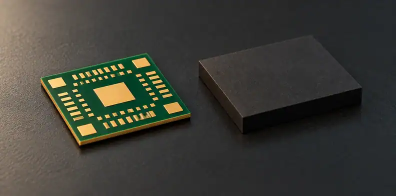
Quick Answer: Before accepting solder resist mold compound adhesion evidence for a BT package substrate, check where the specimen broke and whether its materials, construction and processing match the order. A shear load or solder-mask tape pass alone cannot establish the SR–EMC interface’s acceptance. Published SR–EMC work demonstrates why fracture paths matter, but does not identify a BT laminate.
An adhesion report arrives before your substrate release. Its load looks reassuring, yet the photograph shows exposed copper beneath the solder resist. The number may describe failure at a different interface from the one you need to assess. Read the fracture evidence first, then compare the tested build with the construction on your order. Those are separate decisions, with separate gaps to close.
What does an SR–EMC adhesion report actually measure?
An SR–EMC adhesion report needs to identify the tested specimen, loading method and fracture path before its value can be interpreted. In the cited shear study, a tester sheared molded EMC pins from a defined stack and recorded force in newtons. That specimen-specific result sets no universal acceptance limit, and the study does not identify a BT laminate.
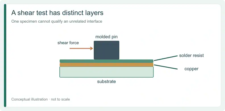
Taiyo's 2025 SR–EMC interface study describes a dry-film solder resist, copper and substrate beneath each molded pin. The pin contacts the resist through a circular base. Its diameter and the layer thicknesses are recorded in the comparison card below.
Keep the reported unit attached to that geometry and loading arrangement. A force in N is not a geometry-independent material property or an MPa acceptance criterion. Ask which interface was exposed after loading before describing the result as SR–EMC strength.
Where did the test specimen actually fail?
Classify the fracture surface before interpreting the load. The specimen may separate between solder resist and EMC, within the resist, between resist and copper, or inside the substrate. An SR–EMC separation directly examines that interface for the tested specimen. Other paths identify a different location that gave way during loading.
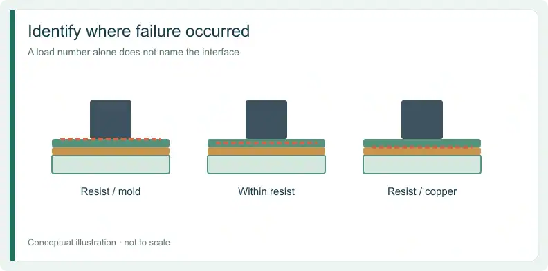
Use this author-proposed fracture-path map with the report. First collect the claimed interface, interfaces actually present, fracture photographs or descriptions, loading geometry and units, conditioning, and the result recorded for each condition. Label observations as test-report data; keep requests for missing information separate from measured results.
| Observed fracture path | What the load describes | Published study example | Suggested evidence disposition |
|---|---|---|---|
| SR–EMC interfacial | Separation at the target interface in that specimen | Table 1: 144.9 N after conditioning; Table 3: 146.1 N | Read for that specimen; still compare construction and criteria |
| Cohesive SR | Failure within the resist | Table 3: 86.8 N | Do not label as target-interface failure strength |
| SR–Cu or substrate | A lower interface or substrate failed first | Table 1: 216.1 N at SR–Cu before conditioning | Ask the owner how the target interface will be isolated |
| Mixed or unreported | Target-interface contribution unresolved | No mixed or unreported example in Tables 1 and 3 | Unknown; hold the interface conclusion pending classification |
Residue on one surface can help the responsible analyst identify the path. Preserve the actual images and classification instead of replacing them with a “pass” label. A different fracture path does not make every shear test invalid; it changes what that particular value can establish.
Why can’t a higher shear load prove a stronger SR–EMC bond?
A higher load can describe failure somewhere else in the stack. Compare the fracture paths, specimen construction and conditions before ranking results. When one specimen fails at SR–Cu and another at SR–EMC, their loads describe different failures. A ratio between them cannot establish the target interface's aging loss or improvement.
Table 1 of the Taiyo study reports 216.1 N with SR–Cu delamination before the study's conditioning, and 144.9 N with SR–EMC delamination after it. Those are path-labelled observations, not two direct measurements of the same interface before and after aging.
Table 3 likewise associates 86.8 N with cohesive SR failure and 146.1 N with SR–EMC separation. Keep the failure labels beside the numbers. The paper also found similar exposed-filler fractions across formulations without identical adhesion behavior. Surface appearance or a process proxy therefore cannot replace the fracture evidence for the condition being assessed.
Does a solder mask tape test cover the mold compound interface?
No. The cited IPC tape method evaluates mask adhesion to printed-board metals and substrate through representative coated coupons and visual material removal. Mold compound is absent from that specimen. A tape pass addresses the mask's attachment beneath it; adhesion between mold compound and the mask's upper surface needs separate evidence.
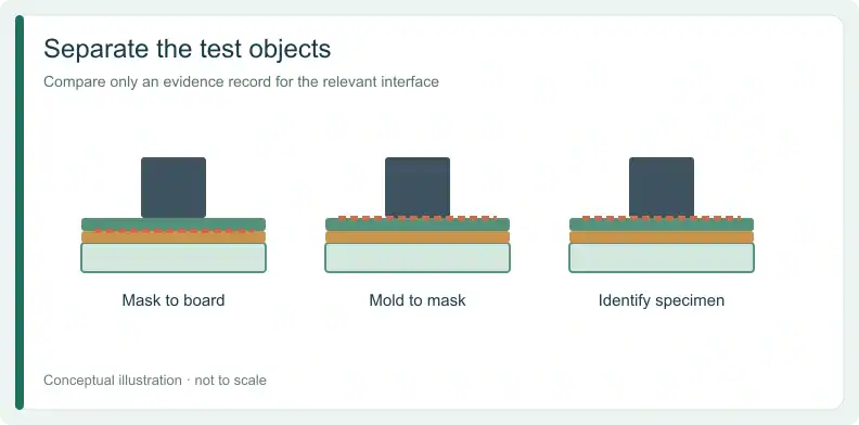
The published IPC-TM-650 2.4.28.1, Revision F (03/07) defines that scope. Check the current revision before invoking it in a purchase requirement. The tape's own adhesion specification is not an SR–EMC bond limit.
QueenEMS' guide to checking mask-to-board adhesion before assembly covers the lower-interface release question. Keep that record, but ask the package owner for evidence addressing the separate molded interface.
Does the tested build match your BT substrate construction?
Compare the report with the ordered SR and EMC products, substrate identity, copper build, geometry, surface history and conditioning. Record differences before deciding whether evidence transfers. The cited study does not name a BT laminate or commercial SR and EMC grades, so applicability to your BT construction remains unestablished by that paper.
This suggested report-to-order card separates disclosed study examples from project records. Fill the empty report and order cells from their actual documents. Mark Documented match only when both records identify the same value or condition; mark Differs for the named owner to assess; keep missing information Unknown. Fracture path and sample information have no order value: carry the fracture-path map’s disposition, and keep sample information Unknown until the report states it.
| Comparison field | Published study example | Your report | Your order | Disposition |
|---|---|---|---|---|
| SR product and revision | Commercial grade not identified | Unknown | ||
| EMC product and revision | Commercial grade not identified | Unknown | ||
| Substrate identity | 800 µm; BT not identified | Unknown | ||
| Copper build and treatment | 18 µm; anchoring varied | Unknown | ||
| SR thickness | 15 µm dry film | Unknown | ||
| Contact geometry | 2.5 mm pin-base diameter | Unknown | ||
| Surface and processing history | Experiment-dependent preparation | Unknown | ||
| Conditioning | Varied by experiment; reported per table | Unknown | ||
| Fracture path | Reported separately by condition | Not applicable | Carry the fracture-path map result; only SR–EMC interfacial proceeds to comparison | |
| Sample count and scatter | Not clearly reported | Not applicable | Unknown until the report states it | |
| Approving owner | Project decision; no study approval | Unknown |
A missing product identity cannot be supplied by a catalogue category or a report about adhesion to copper. Close the specific material or process difference with the acceptance owner. The representative-coupon principle is useful context; the IPC tape procedure does not prescribe an EMC qualification.
Send Gerber files, stackup and fabrication drawing to QueenEMS for a quotation and free DFM review. Identify the SR–EMC evidence owner and unresolved construction fields. Material, process and supporting-evidence availability require project-specific confirmation; add a BOM only if assembly is needed.
Who owns SR–EMC acceptance in a BT package program?
Assign SR–EMC acceptance to the party defining package reliability, usually the package designer with its molding or assembly house. The substrate supplier controls the specified mask and its preparation and cure as built. Agree who sets criteria, molds specimens and approves fracture classification before the results are used for release.
This is a proposed responsibility split; the project agreement identifies the actual owners. The substrate supplier can provide its construction record while the package owner judges whether the interface evidence supports the intended package.
Use the guide to splitting BT acceptance standards between substrate and package owners for that broader boundary. An available board inspection method alone does not establish a qualified SR–EMC pairing.
What can a bare-substrate quote confirm, and what stays open?
A bare-substrate quotation can record the proposed stackup, mask, finish and drawing revision, subject to the fabricator's project confirmation. SR–EMC compatibility, molding results and package qualification require evidence from their agreed owner. Record those items as open when the evidence is missing, rather than inferring them from a board quote.
Ask that the supplier's acknowledgment preserve the named construction and any unresolved interface question. If a material or processing history changes, return that difference to its acceptance owner. Neither a category description nor a completed quotation fills an unknown field in the equivalence card.
Frequently Asked Questions
Does a solder-mask tape pass establish SR–EMC adhesion?
No. The cited tape procedure evaluates mask attachment to board metals or substrate. Its specimen contains no molded EMC. Retain the tape result for its stated scope and obtain separately applicable molded-interface evidence from the package acceptance owner.
Can a higher shear load prove a stronger SR–EMC interface?
Only interpret the load with its fracture path, geometry and conditions. A larger value associated with SR–Cu or cohesive resist failure is not a direct measurement of SR–EMC failure strength. The target-interface comparison remains unresolved when the paths differ.
What details should accompany an adhesion value?
Require the specimen stack and product identities, loading geometry and units, processing and conditioning history, fracture evidence and classification, and the reported sample information. Identify omissions explicitly. The acceptance owner then decides whether the evidence applies to the ordered construction and agreed criteria.
Does the published study set a limit for every BT substrate?
No. Its disclosed specimen does not identify a BT laminate or commercial SR and EMC grades. Its dimensions and loads illustrate a particular experiment. They cannot supply a universal BT acceptance limit or qualify an undisclosed production material pairing.
For a substrate quotation and free DFM review, upload Gerber files with the stackup and fabrication drawing. Include the named mask construction and open SR–EMC evidence questions for project confirmation. Add a BOM only if you also need PCBA assembly.
Upload your files today · Free DFM check before production · Ship worldwide
Get your PCB prototypes in as fast as 24 hours. We handle FR4, Rogers, and hybrid boards, with standard builds up to 24 layers and higher layer counts subject to engineering review — free prototypes for 2–4 layer FR-4 boards, no minimum order.
Just upload your Gerber + BOM — we source every part, assemble, and inspect (AOI + X‑Ray) so you don't have to chase suppliers. PCB assembly typically takes 5–8 working days once all components are in stock. The confirmed delivery schedule is subject to your quotation.