
Quick Answer: Before ordering a GaN dynamic Rds(on) test PCB, record the customer-approved stress history, observation window and board/fixture configuration. Identify the protected geometry, fitted parts and measurement interfaces that support that purpose. Return proposed changes to the test owner, who decides whether the delivered construction and configuration remain applicable.
Featured image: Generic AI-generated illustration; not a QueenEMS board or test result.
This guide covers procurement records; high-voltage operation, clamp or driver design, measurement values and qualification conditions belong to the customer’s approved method. The buyer’s task is to make that method’s hardware assumptions identifiable in the order.
What quantity does a dynamic Rds(on) test board support?
The intended quantity is the GaN device’s on-resistance under a specified switching history and observation window. The PCB supports that measurement through its circuit, connections and fixture interfaces. Its manufactured copper-path resistance is a different quantity. Keep the device result attached to the method and configuration that produced it.
TI’s 2021 GaN reliability white paper explains that dynamic Rds(on) includes charge-trapping effects and that recovery occurs as trapped charge dissipates. A reading taken after a different history or at a different observation time may represent a different device state. The measurement record needs more than the device part number and a resistance value.
The existing bare-board path-resistance guide covers that separate acceptance task. A low-resistance PCB report cannot certify the dynamic device measurement.
Is the board intended for characterization or continuous switching stress?
Identify whether the customer intends a characterization sequence or a continuous switching-stress program. Similar circuit families can support different control sequences and duties. State the intended purpose against the exact board and setup revisions, then have the test owner confirm applicability before a purchasing description treats those uses as interchangeable.
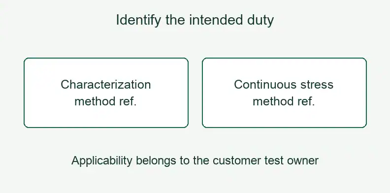
Sandeep Bahl’s TI white paper, Achieving GaN Products With Lifetime Reliability, published in June 2021, shows an energy-recirculating boost-stage test vehicle with clamped drain-source voltage sampling. It describes circuitry resembling a double-pulse arrangement but using different control for continuous switching stress.
The paper also distinguishes TI’s socketed HTOL setup from half-bridge cards used for hard- and soft-switching stress in its program. These are descriptions of TI’s implementations. They neither approve another board for those duties nor establish that every socketed fixture is unsuitable.
Put the intended program or method reference in the order handoff. If an evaluation-board description names characterization only, leave continuous-stress applicability unresolved until its responsible owner provides the evidence.
Which hardware and interfaces need to be frozen before build?
Identify the released PCB construction, fitted population and physical interfaces that the customer’s method assumes. Mark protected switching and sensing geometry, clamp and probe connections, gate-drive parts and fixture connections. Separately identify equipment and configuration data outside the board order so a populated PCB is not mistaken for the complete measurement system.
Keysight’s February 2021 overview, Customized GaN Solutions for Double-Pulse Test, describes a custom board incorporating DC-link and decoupling capacitors, gate drivers, an Rds(on) clamp and probe connections. It also identifies auto-calibration constants associated with the customized implementation. The load inductor is external to the board.
Those details show why the quotation must distinguish physical construction, fitted parts, external hardware and measurement configuration. They are Keysight’s proprietary implementation, not a fabrication recipe or a service offered by a PCB manufacturer.
Ask the design owner to mark which features are protected and reference the released drawing or component definition. The manufacturer can then return a proposed departure against an identified requirement instead of deciding whether an unmarked change preserves dynamic measurement performance.
How should the observation window and temperature basis be recorded?
Attach the approved observation event, window and settling basis to the device result, together with the method reference and actual hardware configuration. Record the named temperature object and how it was obtained. Keep an unsupported transfer or missing timing assumption open for the test owner rather than supplying a default value.
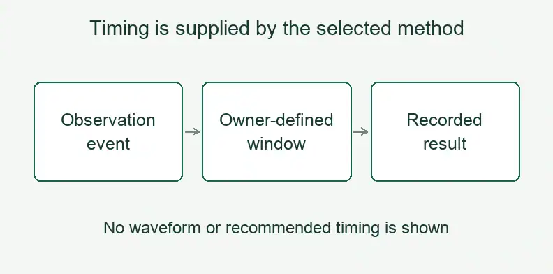
TI’s discussion of trapping and recovery makes the observation timing part of the reported device state. Keysight describes finite settling for its particular clamp implementation and qualifies results by the customized board. Neither example supplies a delay to copy into every purchase specification.
TI also identifies case and junction conditions separately in its hard turn-on examples. Retain the applicable temperature label and method in the record; this handoff supplies no temperature conversion.
The following stress-and-observation boundary record is an editor recommendation. Complete it with customer-approved inputs and references; its empty fields are not missing manufacturer guarantees.
| Field | Entry to provide |
|---|---|
| Purpose and device | Characterization/stress purpose, DUT identity and method revision. |
| Actual configuration | PCB, fitted population, fixture and interface revisions. |
| Approved state | Stress history and operating conditions supplied by the test owner. |
| Physical boundaries | Named voltage/current, probe and clamp connections. |
| Observation | Event, window, settling basis and method source. |
| Temperature | Object, method and unresolved transfer, if any. |
| Responsibility | Raw-data provider, applicability approver and open items. |
Which manufacturing changes should return to the test owner?
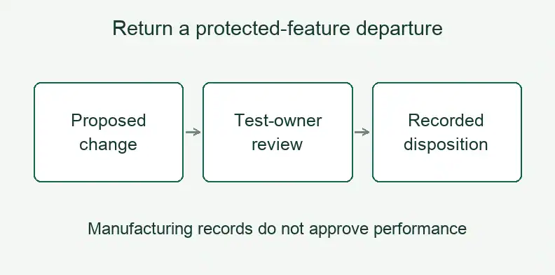
Return departures from protected geometry, stackup, component or interface requirements to the customer’s test owner before accepting them for the intended measurement. Identify the changed feature and revision, the assumption it may affect and the construction evidence available. That owner decides whether the prior method remains applicable or requires further evaluation.
In TI’s illustrated hard-switching model, switched-node capacitance includes PCB overlap capacitance as well as the other device’s output capacitance. This gives a concrete reason to identify geometry assumptions. It does not predict the effect of a proposed change on a different board.
Use this protected-hardware and proposed-change return as a second editorial recommendation:
| Return field | Information to request |
|---|---|
| Protected requirement | Drawing, stackup, component or interface reference. |
| Proposed departure | Changed feature, affected revision and proposed construction. |
| Possible effect | Customer method assumption needing review, without an invented performance estimate. |
| Offered evidence | Fabrication or assembly records available for the proposed build. |
| Owner disposition | Re-evaluation decision, restriction or unresolved item. |
| Release identity | Approver, date and scope for this build or repeat order. |
What does the PCB supplier deliver, and who owns the device result?
The supplier delivers the construction and agreed manufacturing evidence defined by the released files and quotation. Assembly adds the approved fitted population when included in the order. Stress selection, instruments, calibration, observation method and device acceptance remain with the customer or system provider; their evidence must identify the configuration actually evaluated.
Use the ATE PCB manufacturing page for the manufacturing inquiry. Put required fabrication and assembly checks in the quotation rather than assuming that a board order includes fixture design or dynamic device characterization.
Return unresolved method questions to the named test owner. A manufacturing feasibility review can identify a construction question; it cannot close an unsupported dynamic Rds(on) claim.
What else should a GaN test-board buyer confirm? (FAQ)
Keep each answer tied to the intended device, method and hardware configuration. An evaluation-board name, a low-resistance report or a successful build cannot settle every question about the resulting device measurement. Assign unresolved applicability decisions to the test owner before using those records to accept the measurement setup.
Can a low-resistance bare-board test confirm the dynamic Rds(on) setup?
No. It concerns a defined PCB path. The dynamic result belongs to the device under the specified history, observation window and measurement configuration.
Does a double-pulse evaluation board support continuous stress?
Confirm that use with the responsible owner and applicable documentation. A characterization label or similar-looking circuit does not establish the required continuous duty.
Which observation delay should go into the order?
Use the event, window and settling basis supplied by the customer’s selected method. Keep vendor example timing attached to its particular circuit instead of adopting it as a default.
Can a solderless DUT connection replace a soldered one?
Record the actual connection type and fixture revision, then ask the test owner whether the evidence applies. Keysight’s particular connection implementation does not establish equivalence for another setup.
Send your released files for a quote and free DFM review.
Send Gerber, drill data, stackup and drawings for a PCB quote. Mark protected features and the approved boundary and change-return references.
For assembly, add the BOM and drawings for the specified hardware. Agree board checks; dynamic Rds(on) measurement stays with your test owner.