
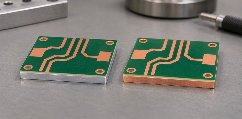
Quick Answer: A copper base PCB substitution can retain the aluminum version’s copper artwork if the finished geometry remains suitable, but it still needs an approved construction revision. Confirm the base specification, dielectric, mechanical features and mating interface before treating the copper version as an equivalent order. Matching Gerber files alone do not establish that equivalence.
Purchasing may receive a copper-base quotation against the same files used for an aluminum board. The visible circuit pattern can match while the material under it, the mounting details and the supplier’s assumptions differ. The useful comparison is between two fully defined constructions. Start with the released aluminum version, identify what the copper proposal changes, and give each change a disposition before the replacement reaches fabrication.
Which part of a metal-base PCB are you changing?
A metal-base PCB has circuit copper, an insulating dielectric and a supporting metal base. An aluminum-to-copper substitution changes that base, while the circuit pattern may remain suitable. Define the changed member in a section view and review the surrounding material and interface requirements as part of the replacement.
Henkel’s Thermal Management for LED Applications guide shows circuit copper, a thermally conductive insulating dielectric and an aluminum or copper base as separate elements. Because the diagram treats the base as its own layer, changing the base is a different decision from increasing the thickness of the circuit foil. The guide is used here for that structural distinction, not as a current availability list or a prediction of temperature improvement.
Start with the word “copper.” It can mean the thin circuit foil, a thick conducting layer, a localized insert or the supporting base. Here it means the base beneath the insulating layer. Mark that member explicitly in the section view so a request for a copper base cannot be interpreted as a request for heavier traces.
Record the specified metal designation rather than leaving “copper” as the entire material callout. Include its required condition where that affects the design, and identify whether the supplier may propose an alternative. The engineering owner should approve that alternative against the intended construction; a material description on a quotation is not an automatic amendment to the drawing.
Then account for the total thickness. If the design fixes finished board thickness, ask how the proposed base and dielectric satisfy it. If only the base thickness is fixed, keep that dimension separate from the finished thickness. A supplier should not have to decide which dimension controls a connector height or a screw engagement.
Exposed base surfaces also need a defined purpose. A surface that contacts a thermal pad, a housing or an electrical contact may have different preparation and finish requirements. Show which face the note applies to. An instruction about circuit-pad finish should not silently become an instruction about the opposite metal face.
For repeat purchasing, preserve both construction identities in the order history. The next buyer should be able to identify which physical version a part number and revision call for without opening an old quotation email.
Which deliverables can stay the same, and which need revision?
Copper-pattern, solder-mask and legend files may remain unchanged when the approved replacement preserves their finished geometry. The fabrication drawing and material definition still need revision because those image files do not fully specify the metal-base construction. Retain an artwork file only after checking it against the proposed build.
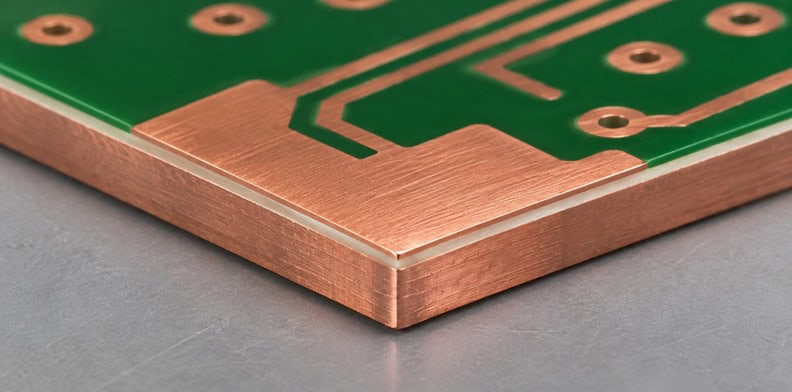
Gerber artwork describes patterns. A copper image identifies where circuit copper remains; it does not, by itself, identify the underlying base alloy or the complete insulation system. The separate drill and profile data also need checking against the finished construction. Sending the old export folder without its drawing leaves the manufacturer to infer those relationships.
| Deliverable | Possible reuse | Required decision for the copper version |
|---|---|---|
| Drill and profile data | Potentially the same coordinates | Check hole function, edge details and drawing consistency |
| Material and stack notes | Retain as the comparison baseline | Issue the approved replacement definition |
This table is an editorial planning aid. For a board mounted to an existing housing, an unchanged outline is only one part of reuse. The finished thickness and the surfaces that locate against that housing must also remain compatible.
Keep the relationship to the native design database clear. If engineering retains the circuit design, the replacement package can identify those retained exports explicitly while issuing a new fabrication drawing. A renamed export folder is a poor substitute for that relationship: it can make an unchanged pattern look revised while leaving the actual material change undocumented.
Does the dielectric have to change with a copper base?
A base-metal change does not automatically require a different dielectric, and it does not prove that the existing dielectric can remain. Ask the fabricator to identify the proposed insulating layer, its finished thickness and its compatibility with the new construction. Approve any substitution separately from the base-metal decision.
The dielectric sits between conducting circuit copper and the metal base. It has an electrical insulation function as well as a role in transferring heat. A proposed copper version that changes this layer is therefore a combined construction change, even if the quotation labels it only as a base upgrade.
Compare material designation, thickness and the relevant published properties under their stated test conditions. “Same thermal grade” does not identify a complete replacement. Where the design requires a particular insulation performance or material approval, keep that requirement visible and ask the supplier to explain how the proposed construction addresses it.
There are two useful quotation cases. In a controlled comparison, the supplier retains the defined circuit and dielectric construction while proposing a different base, where feasible. In an alternative design proposal, the supplier changes both the base and dielectric. Both can be worth reviewing, but they answer different questions and should appear as separate options.
For example, an alternative may offer a thinner insulating layer to meet the same overall board thickness. Engineering then needs to review the insulation and thermal implications of that change. A purchasing comparison that records only “aluminum” and “copper” would hide it.
If keeping the dielectric is a requirement, state it as such and request confirmation. If a change is allowed, define the approval path and the information needed to evaluate it. Keep production press settings with the fabricator; the buyer’s task is to approve the resulting material construction and finished requirements.
Which mechanical features need a new drawing review?
Review every feature that locates, fastens or contacts the board: profile, holes, countersinks, edge condition, flatness and mating faces. Retaining a coordinate file does not establish that the new material meets the same finished requirement. The fabricator and mechanical designer should resolve those features against the actual housing.
Separate coordinates from finished features
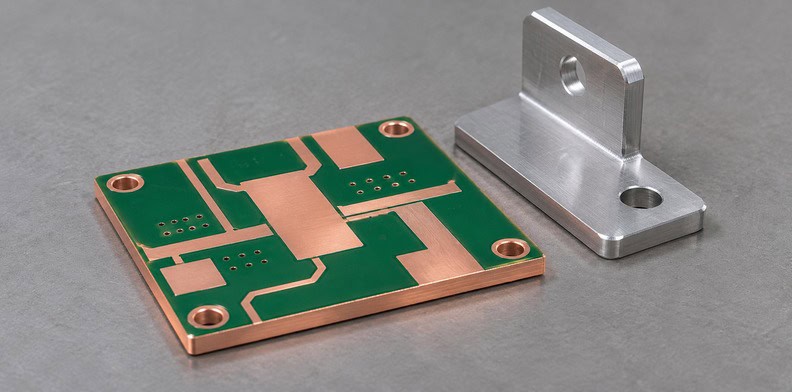
A drill coordinate identifies a location, while the drawing explains whether that location is a clearance hole, a plated electrical connection or a machined feature. Preserve that distinction during substitution. Check a countersink from the correct face and confirm the datum used for its depth, particularly if the finished stack thickness changes.
The board’s conductive base also makes hole function relevant. A hole intended to remain electrically isolated from the base needs a clear construction definition. Use the separate guide to metal-core plated-hole isolation for that topology question rather than assuming that the old drill file establishes the required insulation.
Identify the surface used to locate the board in the assembly. A thickness measurement between two faces and a flatness measurement on one face answer different questions. If the housing contacts only a defined area, show that area rather than leaving the manufacturer to apply a whole-board interpretation to a local contact requirement.
Give the revision a readable disposition
Consider an illustrative replacement with an unchanged copper pattern and outline. Revision A specifies an aluminum base. Revision B proposes copper, retains the circuit artwork and identifies a new material note. The engineer also reviews the mounting-hole section, the base-contact face and the overall thickness. This is a planning example, not a production record.
On the revision drawing, identify the artwork files retained from A, the material note replaced in B and the mechanical requirements confirmed unchanged. If a hole detail is still awaiting supplier review, mark it as unresolved rather than placing it among the retained requirements. Purchasing can then distinguish a quotation request from a released replacement package.
Ask the fabricator to return any proposed machining changes against those specific features. Keep an accepted change in the drawing revision, so the production order does not depend on a machinist finding a quotation attachment.
How do you get two quotations you can compare?
Give both quotations the same baseline and require each proposal to identify its deviations. Compare the quoted construction, manufacturing scope and approval conditions before comparing the total price. A copper version with a changed dielectric or machining requirement should show that difference rather than appearing as an unexplained material premium.
Use the following A/B matrix as an editorial planning aid. Replace its generic entries with the actual released requirements. A blank entry should mean that a decision remains open, not that the supplier may select any convenient construction.
| Item | Aluminum baseline A | Copper proposal B | Disposition |
|---|---|---|---|
| Circuit artwork | Released file revision | Retained or revised file | Confirm finished geometry |
| Base metal and thickness | Specified material and dimension | Proposed material and dimension | Engineering approval |
| Dielectric | Designation and thickness | Identical or named alternative | Review any change separately |
| Mechanical features | Released drawing | Retained or marked deviations | Mechanical disposition |
| Base-facing surface | Finish and contact requirement | Proposed surface condition | Mating-interface review |
| Inspection and supply scope | Agreed requirements and quantity | Same scope or stated exclusions | Resolve before price selection |
Ask whether tooling, material procurement, special machining and the required inspection records are included. Those are quotation scope questions; they do not justify a universal copper-to-aluminum price ratio. PCB lead time also depends on the actual materials and construction, so retain the supplier’s project-specific conditions with each option.
Use the same requested quantity and delivery arrangement for the controlled comparison. A quotation for an initial qualification lot and one for a repeat production lot may allocate setup work differently. Keep those commercial conditions beside the construction matrix so purchasing can explain the difference without attributing every added charge to the new base metal.
If a supplier proposes a third construction, keep it as option C with its own deviations. Do not overwrite the controlled B comparison with a redesign and later attribute the entire price difference to copper.
Before issuing the order, close the unresolved items and identify the approved option by drawing and revision. Retain the other proposal as a quotation record, not an interchangeable manufacturing instruction.
What changes at the assembly and heatsink interface?
Check the finished board’s contact face, flatness, mounting arrangement and thermal-interface material against the existing heatsink or housing. A base replacement may preserve the circuit and still alter that mechanical interface. Evaluate the proposed board under the same defined operating and mounting conditions before accepting it as an equivalent replacement.
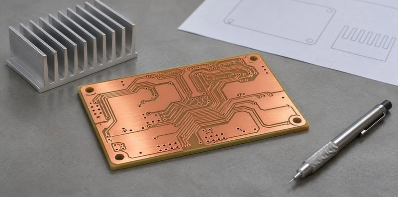
Thermal-interface material is the layer placed between mating surfaces, such as the board base and a heatsink. Its thickness and contact depend on the surrounding mechanical arrangement. Show where it belongs and which drawing defines it. A requirement for the board’s internal insulating dielectric does not also specify this external interface.
Where fasteners provide contact pressure, the mechanical owner should review the fastening arrangement with the changed board construction. Give the fabricator the relevant mating surfaces and finished dimensions; keep the assembled product’s installation conditions with the product design.
If the purpose of the change is thermal improvement, compare the alternatives under the same cooling conditions. The existing complete thermal-path comparison explains that broader analysis. A material change alone does not establish the temperature of a populated board in its enclosure.
QueenEMS (Queenpcb Limited) has more than 10 years of PCB manufacturing experience. Send the original and proposed construction definitions together so the change can be assessed as one request. A particular base material, dielectric combination or machining detail still needs project confirmation; a general capability statement cannot approve the substitution.
Frequently Asked Questions
Is a copper base always better thermally than aluminum?
A copper-base label does not establish the thermal result of the finished product. The insulating layer, component attachment, board geometry, external contact and cooling conditions also affect that result. Compare the actual proposed constructions under the same defined conditions, and identify which part of the heat path the replacement is intended to improve.
Can the replacement keep the same part number?
Use your organization’s configuration-control rules. If the base specification changes, make the approved construction identifiable through the part number, revision or another controlled identifier. A retained copper-artwork filename alone is insufficient to distinguish the two builds during repeat purchasing, inspection or later investigation.
Will the dielectric remain identical after the base change?
Only a confirmed construction proposal can answer that. Ask for the dielectric designation and thickness in both versions. If the supplier proposes an alternative, review it as a separate change against the insulation and thermal requirements. Do not infer identical dielectric from identical Gerber artwork or the same overall board thickness.
Does a base substitution require different testing?
Review the affected requirements before deciding. A changed material or interface may require additional qualification or inspection, while unchanged requirements can remain applicable. Identify the characteristic being checked, the agreed method and the responsible party. Neither a supplier’s general inspection list nor a material datasheet automatically establishes the replacement’s complete qualification plan.
Send your released files for a quote and free DFM review.
Send Gerber, the released stackup and proposed base-metal replacement for review. Identify the construction changes and ask us to confirm feasibility.
For assembly on the revised metal-base board, add the BOM and placement drawing. Flag mounting and thermal-interface changes for project review.