
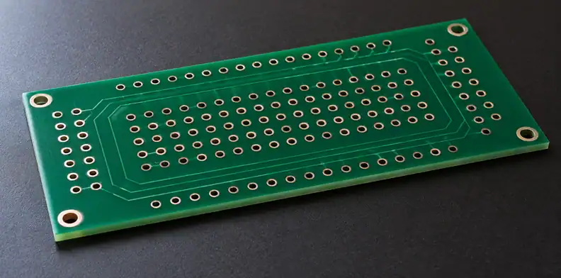
Quick Answer: Metal core PCB plated hole isolation starts by identifying which holes cross the conductive core and which must remain electrically separate from it. One published route uses an oversize opening in the metal, insulating fill and cure, followed by drilling and plating the final hole within that insulation. Agree the actual geometry, materials and verification evidence for your construction; a planar dielectric data sheet alone cannot establish barrel-to-core isolation.
The phrase “two-sided metal-core board” leaves a practical question unanswered: where does each hole run relative to the metal? Resolve that on the stackup before discussing an insulation method. A via above a metal backing, an isolated through-core barrel and an intentional core connection need different drawing instructions.
Which holes actually cross the metal core?
Read each hole's start and stop layers against the actual stackup. It may cross a metal core between circuit layers on opposite sides, connect dielectric layers above a metal backing, or deliberately connect a net to the metal. The label “two-layer” or “double-sided” does not define that electrical relationship.
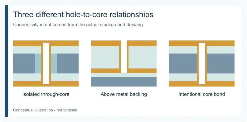
Altium's metal-core design guide distinguishes metal-backed construction from a core with dielectric stacks on both sides. The following comparison is a suggested engineering/procurement aid based on that distinction. It describes connectivity intent, without prescribing a qualified manufacturing sequence.
| Hole/core relationship | What the drawing must show | Isolation question |
|---|---|---|
| Through-core, isolated | A barrel crossing the core, separated by an insulating region | How is separation built and verified? |
| Interconnect above metal backing | Start/stop layers confined to dielectric above the base | Does the specified final drill remain clear of the metal? |
| Intentional core bond | Named connected net and exact connection location | Which connection is required, and which others are prohibited? |
Use the metal-core PCB overview for the broader construction discussion. For the hole decision, retain the section view and connectivity declaration together; either alone can leave the hole’s intended core relationship ambiguous.
How can an oversize opening isolate the plated barrel?
One published route starts with a metal opening larger than the final through-hole. Insulating material fills that opening and cures before the remaining stack is bonded. The final hole is then drilled and plated within the filled region. That leaves an insulating separation between the conductive barrel and the surrounding metal core.
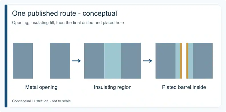
Altium’s metal-core design guide describes this concept in its manufacturing-process section. It supports an explanation of how separation can exist; it supplies no universal opening diameter, fill qualification or remaining-insulation requirement. Treat its sequence as a published example to discuss against the proposed construction.
In a section view, follow the closest approach between the finished barrel and the core. The nominal opening size alone cannot describe that relationship if drilling is off-center or the metal edge has an irregularity. This is geometric reasoning, rather than a reported test result: the final separation depends on the actual boundaries of both conductors.
Ask the fabricator which drawing features define those boundaries and how its proposed route controls them. Keep the agreed response attached to the drawing revision. A statement that a supplier can make “PTH metal-core boards” leaves those construction details unresolved.
Why does planar dielectric leave a hole-wall question?
The dielectric in an insulated metal substrate separates circuit copper from the metal base across their planar interface. Drilling through the base exposes metal along the hole wall. A material description for the flat dielectric therefore does not, by itself, demonstrate an insulating region between a plated barrel and that exposed metal.
The TCLAD IMS anatomy describes the copper circuit, insulating and bonding dielectric, and metal base. Those material roles help explain the stackup. They do not establish the construction or performance of a separately manufactured insulated hole.
Keep two evidence questions separate in the review: whether the specified planar material is correct, and whether the finished hole has the required barrel-to-core separation. The second needs construction-specific evidence. A laminate datasheet, however favorable its electrical values, cannot show where the final drill passed or whether the fill around it is continuous.
How should core bonds and mounting holes be identified?
Declare each intended core connection by net and location. An intentional bond has a different acceptance condition from an isolated signal hole, so a blanket instruction to isolate every plated hole can contradict the design. Non-plated mounting holes also need review because conductive hardware may contact exposed metal even without a plated barrel.
The same design guide mentions through-holes used to bring ground to a metal layer. That establishes intentional connection as a possible design choice. The product's electrical design must decide whether, where and how the core is connected; the example does not require every metal core to be grounded.
For a mounting hole, show the relevant screw, washer, standoff or lead envelope where it affects contact with the core. State whether that contact is intended. The notation “NPTH” describes the absence of hole plating; it does not describe the assembled hardware's electrical relationship to exposed metal. This hardware check is an engineering inference from the geometry, not a universal mounting rule.
Upload the Gerber files and stackup or drawing for a quotation and free DFM review. Mark each hole family’s core relationship and identify construction or verification details that still need agreement. A BOM is needed only for requested assembly.
What belongs in a metal core PCB plated hole isolation map?
Group holes by shared purpose, layer span and intended core relationship, then connect each family to its drawing location and evidence requirement. Record isolated, connected and non-intersecting families explicitly. Assign an owner to every unresolved geometry or test question so that an unanswered field remains visible at the release decision.
This hole-family isolation evidence map is a suggested engineering/procurement aid. Populate it for your board; its entries are prompts, not acceptance values or a supplier procedure.
| Record field | Information to enter | Question it closes |
|---|---|---|
| Family and locations | Hole identifiers, coordinates or drawing callouts | Which physical holes share this requirement? |
| Purpose and layer span | Signal, power, mounting or bond; start/stop layers | Does the path intersect or approach metal? |
| Core relationship | Isolated, intentionally connected, or non-intersecting | What electrical result is intended? |
| Core net | Named net, or declared isolation intent | Relative to which conductor is the test meaningful? |
| Insulating geometry | Agreed drawing features and material identification | What separation must the construction provide? |
| Evidence | Representative section and defined electrical checks, as agreed | What does each record demonstrate? |
| Open item and owner | Missing decision, responsible party, disposition | What prevents release? |
Separate families when their core relationship differs, even if their finished hole diameters match. An isolated component lead and a deliberate core bond cannot share an undifferentiated pass condition. Likewise, a mounting family needs its hardware-contact decision recorded separately from a signal via's barrel isolation.
What do sections and electrical tests each establish?
A section shows geometry at the location examined; an electrical test shows behavior under its stated conditions. Neither record substitutes for the other. An open/short result does not establish a specified withstand performance or service life, and a satisfactory local section does not prove that every hole in the lot has the same geometry.
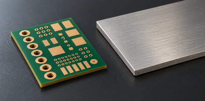
As a suggested verification approach, agree what a representative section should reveal: the barrel, metal edge, intervening insulation and any relevant voids, burrs or eccentricity. State how the section or coupon relates to the delivered hole family. Record the sampling scope rather than allowing “section checked” to imply inspection of every hole.
For electrical evidence, name the conductors tested, test type, conditions and acceptance criteria. If withstand testing is required, the design authority must establish the applicable voltage, dwell and leakage criteria. Where the product has high-voltage isolation requirements, coordinate them using the high-voltage PCB requirements guide. No numerical test condition is supplied here; agree in the quotation who performs any such test and how results are reported.
Which open items need agreement before fabrication?
Resolve the opening-to-hole relationship, insulating material, remaining separation requirement and evidence scope against the actual drawing revision. Include controls for relevant voids, burrs, drill offset and exposed metal, plus the representative section location and electrical-test conditions. Each value or disposition needs project-specific agreement; copying a generic diagram cannot complete this release record.
Before release, reconcile the hole-family map with the fabrication drawing and net intent. If an item remains unknown, identify who can approve the proposed construction or require more evidence. Keep the decision and its revision reference with the order so a later hole, material or stackup change can be reviewed against the same intent.
QueenEMS has more than 10 years of experience. Attach the marked hole-family drawing to the Gerber package and stackup when you request a quotation with free DFM review. Supply a BOM if assembly is included in your request, and confirm the proposed construction and evidence scope before ordering.
Frequently Asked Questions
Does the IMS dielectric insulate the inside of a drilled hole?
Not by itself. The laminated planar layer does not establish hole-wall insulation. A drill through metal exposes a metal wall, so an isolated barrel needs a construction that separates it from that wall. The published insulating-fill route is one conceptual example, subject to project-specific agreement.
Is a two-layer metal-core PCB always a through-core design?
No. Both routing layers may sit above a metal backing, or circuit layers may sit on opposite sides of a core. Read the actual stackup and the hole's start and stop layers rather than inferring its path from a layer-count label.
Does a passing electrical test prove core isolation?
Only within its defined scope. A pass establishes the result under the specified test conditions, not beyond them. Routine continuity and open/short checks differ from a defined isolation or withstand test. Review the tested conductors, conditions and criteria alongside representative construction evidence.
Should every plated hole be isolated or the core grounded?
No blanket rule covers both decisions. The design must name intended core connections and identify the holes that require isolation. Mounting hardware also needs a declared relationship to exposed metal; an NPTH label alone does not answer that question.
Upload your files today · Free DFM check before production · Ship worldwide
Get your PCB prototypes in as fast as 24 hours. We handle FR4, Rogers, and hybrid boards, with standard builds up to 24 layers and higher layer counts subject to engineering review — free prototypes for 2–4 layer FR-4 boards, no minimum order.
Just upload your Gerber + BOM — we source every part, assemble, and inspect (AOI + X‑Ray) so you don't have to chase suppliers. PCB assembly typically takes 5–8 working days once all components are in stock. The confirmed delivery schedule is subject to your quotation.