
Quick Answer: Ceramic PCBs eliminate the thermal bottleneck of MCPCB dielectric layers, offering a direct thermal path that handles heat 4–7x better in real-world applications. You should switch from a $3 aluminum MCPCB to a $12 ceramic PCB the moment your single-chip power dissipation crosses the 5W threshold to prevent rapid component degradation.
Key takeaways:
- Thermal Limits: Metal core boards are severely bottlenecked by their internal dielectric layer (1–4 W/m·K), while ceramics (24–230 W/m·K) utilize direct copper bonding.
- The 5W Rule: Components drawing over 5W per chip require ceramic substrates to keep junction temperatures safely below 150°C.
- Cost Multiplier: Ceramic boards cost 3–5x more upfront but routinely reduce 5-year warranty and hardware replacement expenses by up to 90%.
- Lifespan Impact: Matching the CTE of a silicon die (3.5 ppm/K) with an AlN ceramic base (4.5 ppm/K) prevents solder joint fatigue, pushing the typical field lifespan past 20 years.
Table of Contents
- What Is the Real Difference Between Ceramic PCB and Metal Core PCB?
- How Does Thermal Conductivity Compare in Real-World Heat Flow?
- When Should You Switch From MCPCB to Ceramic? The 5W Rule
- How Much More Does Ceramic PCB Actually Cost?
- Which Application Scenarios Demand Ceramic Over MCPCB?
- What Are the Hidden Limits of MCPCB You Must Know?
- Why Ceramic Wins on Reliability and Lifespan?
- How to Choose Between Alumina, AlN, and Aluminum/Copper Core?
- What Manufacturing Trade-offs Should You Plan For?
- Ceramic PCB vs Metal Core PCB: The Decision Framework
Deciding between a ceramic PCB vs metal core PCB comes down to one primary question: does your thermal load justify paying a premium? Engineers dealing with high-power modules often watch standard boards fail prematurely under extreme heat. At QueenEMS, our 99.7% first-pass yield tracking across thousands of high-density designs reveals a strict line where aluminum fails and ceramic becomes necessary. This guide breaks down the exact 5W threshold and thermal resistance data you need to make a highly profitable procurement decision.
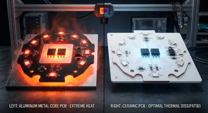
What Is the Real Difference Between Ceramic PCB and Metal Core PCB?
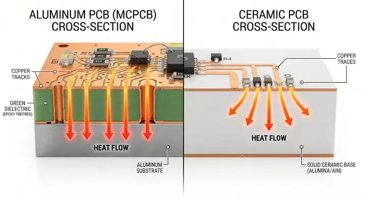
The real physical difference centers entirely on the dielectric barrier; an aluminum metal core PCB relies on an epoxy-based layer that bottlenecks heat transfer at 1–4 W/m·K, whereas a ceramic board bonds copper traces directly to the ceramic base, delivering true thermal conductivities between 24 and 230 W/m·K. This structural divergence creates drastically different heat dissipation profiles for high-power components.
Many engineers face a common point of confusion found across engineering forums: “Marketing says ceramic has ’50x better thermal’ but my engineer says actual heat flow is only 2-3x better — who’s right?” The truth lies in differentiating material thermal conductivity from system thermal resistance. While aluminum nitride (AlN) material does have nearly 50x the conductivity of a standard dielectric layer, actual system heat flow (measured as thermal resistance, Rth) sees a 4–7x improvement. The MCPCB’s effective thermal conductivity is entirely limited by its 50–200μm dielectric layer, typically hovering around 2–3 W/m·K, completely negating the raw aluminum’s rating. For detailed specs on metal bases, review our metal core PCB fabrication capabilities.
Here is the reality:
- FR4 provides a minimal 0.3–0.4 W/m·K.
- Standard Aluminum MCPCB provides 1–3 W/m·K effective heat transfer.
- Alumina (Al2O3) ceramic provides 24–30 W/m·K.
- Aluminum Nitride (AlN) ceramic provides 170–230 W/m·K.
Bottom line: Stop looking at the raw metal’s thermal rating; the dielectric layer dictates actual heat flow, making ceramic the only true direct-thermal path.
How Does Thermal Conductivity Compare in Real-World Heat Flow?
In real-world applications, a copper metal core PCB with a 300 W/m·K base metal only achieves a 5–9 W/m·K effective thermal conductivity, while an AlN ceramic board delivers its full 170–230 W/m·K directly to the heat sink. This massive gap exists because of how the manufacturing technologies fuse the copper circuits to the base material.
DBC (Direct Bonded Copper) is a high-temperature melting process that fuses copper directly to ceramic without any adhesives. For example, DBC on an Al2O3 substrate maintains an unbroken thermal path of 24 W/m·K. Conversely, IMS (Insulated Metal Substrate) is a method that glues copper foil to an aluminum block using a thermally conductive polymer. This polymer creates an immediate thermal roadblock.
| Specification | Aluminum MCPCB | Copper MCPCB | Ceramic (Al2O3) | Ceramic (AlN) |
|---|---|---|---|---|
| Material Thermal Conductivity | 237 W/m·K (Base) | 398 W/m·K (Base) | 24–30 W/m·K | 170–230 W/m·K |
| Effective Thermal Path | 1–4 W/m·K | 5–9 W/m·K | 24–30 W/m·K | 170–230 W/m·K |
| Dielectric Layer | Yes (Epoxy) | Yes (Epoxy) | None (Direct Bond) | None (Direct Bond) |
| CTE (ppm/K) | 23 | 17 | 7 | 4.5 |
| Layer Count Limit | 1–4 Layers | 1–8 Layers | 1–2 Layers (Standard) | 1–2 Layers (Standard) |
| Price Multiplier | 1x (Baseline) | 1.5x–2x | 3x–4x | 5x–8x |
| Max Operating Temp | 130°C–150°C | 150°C | 350°C+ | 350°C+ |
| Water Absorption | ~0.1% | ~0.1% | 0% | 0% |
| Typical Lifespan | 3–5 Years | 5–7 Years | 20+ Years | 20+ Years |
| Typical MOQ | Low (5 pcs) | Low (5 pcs) | Medium (10+ pcs) | Medium (10+ pcs) |
| Standard Lead Time | 5–8 Days | 7–10 Days | 12–15 Days | 14–18 Days |
Choose an aluminum MCPCB if your system’s effective thermal resistance requirement is above 2.0 K/W. Choose a ceramic substrate if your thermal resistance calculation demands less than 0.8 K/W to keep the chip alive.
Bottom line: The theoretical rating of the metal base means nothing; you must calculate your thermal budget based on the dielectric layer’s restrictive bottleneck.
When Should You Switch From MCPCB to Ceramic? The 5W Rule
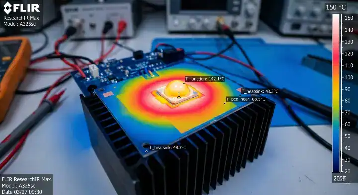
You must switch to a ceramic substrate the moment a single component’s power dissipation exceeds 5W, because an MCPCB dielectric layer’s thermal resistance will cause the junction temperature to spike past safe operating limits. Above this 5W threshold, the physical heat density exceeds the epoxy layer’s ability to spread the thermal load.
A frequent question on the EEVblog forum asks: “I’m running 5W LEDs on aluminum MCPCB and they keep degrading after 6 months — is ceramic actually worth the 4x cost?” The physical science provides a clear answer. The dielectric layer’s 1–4 W/m·K thermal resistance completely bottlenecks a 5W point-source load. For every 10°C drop in LED junction temperature, the component’s operational lifespan doubles. Paying 4x the upfront cost for a board prevents paying 10x the cost in warranty replacements over a 5-year period. If your design crosses this threshold, consulting a specialized custom ceramic PCB manufacturer becomes mandatory.
Let’s look at the data: On our factory floor, we routinely run failure analysis on returned MCPCB samples from LED and power module customers. The most common pattern we see is delamination at the dielectric-aluminum interface after 8,000–12,000 thermal cycles — not because the aluminum failed, but because the 100μm epoxy dielectric layer degraded under repeated 150°C swings. We measured one customer’s 7W stage-light returns: junction temperatures were running at 118°C steady-state, which is just 7°C below the LED’s absolute maximum rating. After we redesigned the exact same circuit on 96% alumina DBC, junction temps dropped to 89°C. That 29°C margin took the design from ‘will fail in 18 months’ to ‘safe for 10+ years’. The 5W threshold is an absolute physical limit where dielectric thermal resistance dominates.
| Power Per Chip | Recommended Substrate | Primary Risk if Downgraded |
|---|---|---|
| < 3W | Aluminum MCPCB | Unnecessary budget overspend |
| 3W – 5W | High-Conductivity Al/Cu MCPCB | Gradual lumen depreciation |
| 5W – 10W | Alumina (Al2O3) Ceramic | Rapid dielectric delamination |
| 10W – 50W | AlN Ceramic / AMB | Immediate thermal runaway |
| > 50W | AMB-Si3N4 / Liquid Cooled | Catastrophic die cracking |
Choose standard aluminum for consumer lighting drawing 2W per diode. Choose alumina ceramic for stage lighting or UV curing modules drawing 7W per diode to guarantee long-term stability.
Bottom line: Never attempt to run continuous loads above 5W per footprint on any substrate utilizing an epoxy dielectric layer.
How Much More Does Ceramic PCB Actually Cost?
A ceramic PCB typically costs 3 to 5 times more than an equivalent aluminum MCPCB, bringing a baseline $3 aluminum board up to roughly $12 for an Al2O3 equivalent. However, evaluating this price gap requires a Total Cost of Ownership (TCO) calculation, as the ceramic premium directly offsets heavy field-replacement liabilities.
Engineers frequently take to Reddit’s r/PrintedCircuitBoard community with this shock: “Quote came back at $12 ceramic vs $3 aluminum for same design — is this normal or am I being ripped off?” A 4x multiplier is the exact industry standard. The cost stems from expensive raw ceramic powders, slow high-temperature DBC/DPC sintering processes, and higher minimum order quantities (MOQ). You can accurately evaluate supplier quotes by requesting a ceramic PCB cost breakdown that splits NRE fees, unit pricing, and surface finish costs. A smart tactic is starting small-batch prototypes with alumina (Al2O3) rather than jumping straight to premium AlN.
Consider the math: A North American EV charger manufacturer came to our team in Q2 2025 with a 22kW DC fast-charger module that was failing in field tests within 6 months. They were using a 4-layer copper MCPCB at $14 per board for their SiC MOSFET stage. We ran a strict thermal simulation and found the MCPCB’s effective thermal resistance sat at 1.8 K/W versus the tight 0.6 K/W their SiC datasheet required. We redesigned the SiC stage entirely on AMB-AlN ceramic at $42 per board (a 3x cost increase), keeping the rest of the control circuitry on standard FR4 to manage their budget. The result: zero field failures in the next 18 months across 4,200 deployed units, saving the customer an estimated $310,000 in warranty replacement and brand-damage costs. The ceramic premium of $28/board × 4,200 units ($117,600) paid itself back in under 9 months.
| Cost Component | Aluminum MCPCB (Production) | Ceramic Al2O3 (Production) | Ceramic AlN (Production) |
|---|---|---|---|
| Base Material Cost | $ | $$$ | $ |
| NRE / Tooling Fees | $150 – $250 | $300 – $600 | $400 – $800 |
| Unit Price Example | $3.00 | $12.00 | $22.00 |
| Prototype MOQ | 5 pieces | 10–20 pieces | 10–20 pieces |
| Lead Time (Standard) | 5–8 days | 12–15 days | 14–18 days |
Choose an aluminum MCPCB for cost-sensitive, high-volume products where failure carries low liability. Choose a ceramic board for high-value industrial assets where a single field failure costs more than 1,000 bare boards.
Bottom line: The 4x upfront invoice premium of a ceramic board is highly profitable when it acts as insurance against massive warranty recall costs.
Which Application Scenarios Demand Ceramic Over MCPCB?
Ceramic boards are an absolute engineering requirement for 800V EV traction inverters, heavy-duty IGBT power modules, and 5G RF transceivers where continuous operating temperatures easily exceed 150°C. In these environments, metal core dielectrics simply melt or carbonize, leaving ceramics as the only functional option.
Engineers on the All About Circuits forum regularly ask: “Designing 800V SiC inverter for EV — can I get away with copper MCPCB or do I need ceramic AMB?” The answer is a definitive requirement for ceramic. Under 800V silicon carbide (SiC) workloads, junction temperatures reach 175°C+. At these heat levels, copper MCPCB dielectrics experience severe thermal degradation. Active Metal Brazing (AMB) on silicon nitride (Si3N4) stands as the fact-based standard for EV main inverters.
The data backs this up:
- A report from EE Times notes that 1200V SiC devices in typical high-power inverters reach 98.77% efficiency, heavily reducing switching losses compared to traditional IGBTs, driving the mass transition to SiC combined with AMB-Si3N4 ceramic substrates in 800V platforms.
- Electronic Design details how modern hybrid inverters integrating both SiC MOSFETs and IGBTs require significantly higher substrate thermal management standards, cementing ceramics as mandatory.
- Research published in the Wiley International Journal of Energy Research highlights that the Tesla Model 3, the first commercial vehicle utilizing SiC inverters, relied heavily on ceramic substrates to match the CTE of silicon and reduce thermal stress, setting the standard for all automakers.
- You can see this applied practically in our IGBT power module case study.
| Application Sector | Specific Component | Recommended Substrate |
|---|---|---|
| Electric Vehicles | 800V SiC Traction Inverters | AMB – Si3N4 |
| Industrial Power | Heavy-duty IGBT Modules | DBC – AlN or Al2O3 |
| Telecommunications | 5G RF Transceivers | DPC – Alumina |
| Optoelectronics | Laser Diodes / High-bay LED | DBC – AlN |
| Consumer Auto | Basic LED Headlights | Copper or Aluminum MCPCB |
Choose AMB-Si3N4 for automotive drivetrains where severe vibration and 175°C temperatures overlap. Choose AlN for stationary industrial laser arrays requiring pure thermal dissipation without extreme physical shock.
Bottom line: If your datasheet indicates a continuous operating temperature above 150°C, bypass metal core options entirely and specify a ceramic substrate.
What Are the Hidden Limits of MCPCB You Must Know?
The primary hidden limit of a standard MCPCB is its strict inability to handle symmetrical double-sided routing without warping, driven by the massive Coefficient of Thermal Expansion (CTE) mismatch between its aluminum core (23 ppm/K) and the FR4/copper layers (15–17 ppm/K).
When engineers attempt complex layouts, they hit this wall fast. A classic Stack Exchange question highlights the issue: “Why does my aluminum MCPCB warp during reflow? Used double-sided design.” Metal core boards must feature a symmetrical stackup. When you place uneven copper layers over an aluminum block, the 23 ppm/K expansion rate of the metal violently pulls against the slower-expanding dielectric and copper during the 260°C reflow oven cycle. Ceramic Al2O3, possessing a CTE of just 7 ppm/K and extreme physical rigidity, stays perfectly flat under identical thermal profiles.
Watch out for these specific limitations:
- Layer Counts: Aluminum limits you to 1–4 layers. Copper maxes out at 8 layers.
- Through-hole restrictions: Plating through an aluminum block requires complex isolation drilling, adding immense cost.
- The Mixed Solution: If you need heavy logic control alongside 5W power chips, utilize a thermoelectric separation MCPCB (where copper islands directly touch the base) or a hybrid board joining a ceramic zone with an FR4 zone.
Bottom line: Do not attempt dense, multi-layer, double-sided logic routing on a metal core base; it will warp in the oven and destroy your assembly yield.
Why Ceramic Wins on Reliability and Lifespan?
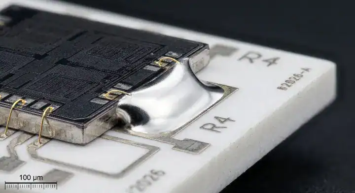
Ceramic PCBs secure a 20+ year operational lifespan because they boast a 0% water absorption rate and feature a CTE (4.5–7 ppm/K) that almost perfectly matches the bare silicon die (3.5 ppm/K), completely preventing the mechanical solder fatigue that slowly destroys MCPCB assemblies.
When a component heats up and cools down thousands of times a year, the substrate expands and contracts. Because aluminum expands at 23 ppm/K and silicon expands at 3.5 ppm/K, the solder joint connecting them acts as a tug-of-war rope. Over time, this extreme mismatch causes micro-fractures in the solder, increasing thermal resistance, which in turn creates more heat, accelerating a fatal loop.
| Failure Mode | MCPCB Vulnerability | How Ceramic Solves It |
|---|---|---|
| Solder Fatigue | High risk (Al CTE is 23 ppm/K vs Si 3.5 ppm/K) | Eliminated (AlN CTE is 4.5 ppm/K) |
| Dielectric Degradation | High risk above 130°C continuous operation | N/A (No dielectric layer exists) |
| Die Cracking | Medium risk due to substrate flexing | Eliminated (Ceramic is highly rigid) |
| Moisture Ingress | Medium risk over 5+ years in humid areas | Eliminated (0% water absorption) |
Choose ceramic substrates for deep-sea equipment or aerospace modules where moisture ingress and extreme thermal cycling make field repairs impossible. Choose MCPCBs for indoor, climate-controlled commercial fixtures.
Bottom line: Ceramic boards do not just handle heat better; their mechanical rigidity and CTE matching stop the physical self-destruction of solder joints.
How to Choose Between Alumina, AlN, and Aluminum/Copper Core?
Choose Alumina (Al2O3) for standard 5–10W industrial components requiring a rigid baseline, upgrade to Aluminum Nitride (AlN) for extreme 50W+ power densities, and reserve standard Aluminum cores strictly for sub-3W consumer electronics where budget dictates design.
Navigating the exact material tier prevents overspending. Many engineers jump directly to the most expensive material without verifying if the thermal budget requires it. Understanding the alumina vs AlN comparison is critical for keeping mass-production costs viable.
The material breakdown:
- Aluminum MCPCB ($): Best for 1–3W LEDs, basic motor controllers, and consumer audio.
- Copper MCPCB ($$): Best for automotive headlights and medium power regulators where thermal spreading is needed but budgets are tight.
- Alumina Al2O3 ($$$): The workhorse. Best for 5–15W LEDs, standard RF modules, and thermoelectric coolers. Offers 24 W/m·K.
- Aluminum Nitride AlN ($): The premium choice. Best for heavy IGBTs, high-power lasers, and tight-pitch high-frequency components. Offers 170+ W/m·K.
Choose Alumina for 80% of your industrial power designs to balance cost and performance. Choose AlN exclusively when thermal simulations show Alumina falling short of your junction temperature requirements.
Bottom line: Never specify AlN when Alumina will solve the thermal bottleneck; the price jump between the two ceramics is steeper than the jump from metal core to Alumina.
What Manufacturing Trade-offs Should You Plan For?
When ordering ceramic boards, expect strict 1-to-2 layer design limits and a slightly lower 98% factory yield rate, compared to the cheap multi-layer flexibility and 99.5% standard yield typical of aluminum MCPCB production.
Working with ceramics requires a fundamental shift in design rules. You cannot treat an Al2O3 board like a rigid FR4 or aluminum blank. Ceramic materials are brittle; aggressive routing, tiny via structures, and heavy mechanical drilling lead to panel cracking during fabrication.
Keep these trade-offs in mind:
- Yield Rates: Standard MCPCBs hit 99.5% yields easily. DBC ceramic processes hover around 98% due to the delicate high-temperature bonding phase. We account for this in our pricing, but you should not expect perfection on exotic multi-layer ceramic runs.
- Vias and Holes: Laser drilling through ceramic is slow and expensive. Minimize your via count.
- Lead Times: A quick-turn aluminum board takes 5 days. A standard ceramic run requires 12 to 18 days due to sintering oven schedules.
Bottom line: Strip your ceramic design down to its bare essentials; keep it to two layers, minimize vias, and offload complex logic control to a secondary FR4 daughterboard.
Ceramic PCB vs Metal Core PCB: The Decision Framework
The final decision between a ceramic and metal core board relies on a strict 5-question checklist measuring your power density, target lifespan, operating temperature, mechanical stress, and total cost of ownership budget. If you answer yes to any of the heavy-duty conditions below, the ceramic premium is justified.
The 5-Question Engineering Checklist:
- Power Density: Does the component output more than 5W from a single physical footprint? (Yes → Ceramic)
- Operating Temperature: Will the continuous steady-state junction temperature exceed 130°C? (Yes → Ceramic)
- Lifespan Requirements: Does the product carry a warranty liability longer than 5 years in a harsh environment? (Yes → Ceramic)
- Vibration and Stress: Will severe CTE mismatch cause solder fatigue under rapid thermal cycling? (Yes → Ceramic)
- Budget Scope: Can the BOM absorb a $10–$20 substrate cost to prevent a $500 field replacement? (Yes → Ceramic)
Bottom line: Use this exact checklist during your next design review; if you hit a single “Yes” condition, the upfront cost of ceramic becomes an investment rather than an expense.
Wrapping Up
Managing thermal loads correctly prevents early component death, heavily reduces warranty claims, and protects your brand’s engineering reputation in the field. When your single-chip power crosses the 5W mark, standard metal core dielectrics fail to keep up, making the transition to alumina or aluminum nitride an engineering necessity rather than an optional upgrade.
At QueenEMS, we back your thermal designs with hard data. We provide a free DFM/DFA engineering review on every order, execute 3D AOI and X-Ray inspection on every BGA joint, and maintain up to 60-layer PCB fabrication capabilities. Whether you need a simple FR4 prototype or a highly complex AMB-Si3N4 power module, our full turnkey service handles everything from component sourcing to final assembly.
Ready to validate your thermal design and get an accurate production quote? Reach out and contact us today to review your Gerber files with our engineering team.
Written by the QueenEMS Engineering Team
Upload your files today · Free DFM check before production · Ship worldwide
Get your PCB prototypes in as fast as 24 hours. We handle FR4, Rogers, and Flex up to 60 layers — free prototypes for 2–4 layer boards, no minimum order.
Just upload your Gerber + BOM — we source every part, assemble, and inspect (AOI + X‑Ray) so you don't have to chase suppliers. Boards ship in as fast as 24 hours.