
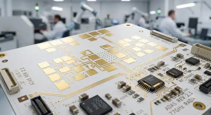
Quick Answer: Shengyi mmWave77 is a ceramic-filled PTFE laminate offered for RF applications, including automotive radar. Its published process Dk of 3.00 ± 0.04 and loss tangent of 0.0010 are measured at 10 GHz and 23°C; they do not certify an unchanged antenna layout at 77 GHz. A replacement decision needs the actual dielectric thickness, copper foil, circuit measurements, bonding system and qualification requirements.
A mmWave77 substitution starts with the approved radar construction, not a comparison of two nominal Dk numbers. Changing the laminate may affect the antenna, transmission lines, plated holes and assembly even when the circuit artwork remains unchanged. The practical question is whether the proposed build meets the existing electrical and reliability limits with an acceptable procurement cost.
Ceramic-filled PTFE is also different from a solid alumina or aluminum nitride circuit substrate. The ceramic particles are part of a polymer composite. For a broader comparison of substrate families, the PCB materials overview provides the surrounding material choices. Keep those families separate when preparing a drawing or requesting a quotation.
Table of Contents
- Read the mmWave77 data at the stated test conditions
- Compare the complete RF construction, not the resin label
- Qualify a replacement with the same reference circuit
- Specify the hybrid stackup and bonding system
- Review fabrication records for the proposed material
- Keep automotive approval separate from material identity
- Compare the cost of accepted boards
- Prepare the radar build for quotation
Read the mmWave77 data at the stated test conditions
Use the manufacturer’s published values as a characterized starting point, with their test conditions attached. The product name does not change the frequency at which a particular property was measured.
What the published numbers establish
Shengyi’s mmWave77 product data lists process Dk 3.00 ± 0.04 and loss tangent 0.0010 using IPC-TM-650 2.5.5.5 at 10 GHz/23°C. The same page labels its tabulated values as typical reference information rather than specification limits. Procurement should therefore obtain the current controlled specification and ordered construction instead of copying the whole public table into an acceptance drawing.
The distinction matters at RF design review. A nominal value can help identify a candidate material, but an engineering model also needs to describe the frequency range, thickness and metal surfaces actually used. A public typical value is not a guarantee that every board in a delivered lot reproduces a particular antenna phase response.
| Item to carry into the comparison | Information to retain | What it cannot establish alone |
|---|---|---|
| Process Dk | Value, test method, frequency and temperature | The final antenna resonance |
| Loss tangent | Measurement conditions and material revision | Total feed-network insertion loss |
| Dielectric thickness | Ordered thickness and tolerance | Finished impedance without conductor geometry |
| Copper specification | Foil type, thickness and surface treatment | Loss after plating and final finish |
| Qualification requirement | Construction, exposure and acceptance criteria | Approval of a different stackup |
Process Dk is not an antenna model
Process Dk is associated with a material test. A design value may be extracted from a particular circuit or supplied for a particular simulation method. They should not be treated as interchangeable labels for a universal constant. Rogers discusses the interaction between design Dk, circuit measurements and copper roughness; its discussion explains the modeling issue, not a mmWave77-specific design value.
Ask which value the RF engineer intends to use, where it came from and what geometry supports it. Do not import another laminate’s design Dk simply because both products publish a similar process Dk. Missing operating-band characterization is a reason to plan a measurement, not to assert that the materials behave identically.
Compare the complete RF construction, not the resin label
Compare the candidate and approved material using the same electrical objective and a defined physical cross-section. A shared material family narrows the investigation but does not finish it.
Copper and geometry change the comparison
Keep the dielectric thickness, finished line width, conductor thickness, reference-plane spacing and solder-mask coverage visible in the comparison. Include the proposed copper foil and finished conductor surface. A loss measurement on one construction cannot be assigned to another solely by matching the laminate name or nominal thickness.
A supplier’s “same stackup” response should identify which dimensions are actually unchanged and which are only nominally similar. For example, a different copper build-up can alter the etched cross-section even when the artwork uses the same trace width. An antenna designer needs that distinction before interpreting any apparent material improvement or degradation.
Separate trace loss from launch loss
A measured transmission result may include connectors, probes, launches, vias and mismatch as well as the line being investigated. Document the calibration and reference planes before comparing results. Otherwise a better connector attachment can be mistaken for a lower-loss laminate, or a damaged launch can disqualify a suitable material.
Use a circuit coupon and its measurement drawing to state exactly what is included. A straight-line coupon can support a transmission-line comparison; it does not by itself qualify the complete antenna array, radome or radar module. Keep those acceptance tests separate so the team can identify the source of any failed margin.
Qualify a replacement with the same reference circuit
Build a controlled comparison that changes the proposed laminate construction while holding other influential variables steady. The result should let the RF engineer distinguish a material effect from a fabrication or fixture effect.
Start with an approved baseline board and the corresponding fabrication files. Record the material revision, copper option, stackup, measurement setup and assembly state for that baseline. Build the candidate with the same reference structures wherever possible. A historical plot without those identifiers is useful background but is a weak basis for accepting a substitute.
Compare results over the operating band and the specified temperature range. Include insertion and return loss, phase or electrical length where relevant, and the antenna measurements needed by the system specification. The required limits belong to the radar design; this article does not assign a universal dB-per-inch number or an allowable phase error to every application.
A useful comparison log has one row for each measured feature: baseline result, candidate result, measurement uncertainty, applicable limit and disposition. Where a candidate misses a limit, record the suspected cause before changing the artwork. Altering the material, trace width and launch in the same build makes it harder to determine which change produced the result.
Identify coupon locations on the fabrication panel as well as the tested serial numbers. This lets the engineer investigate position-dependent geometry changes instead of treating every difference as a material property.
Keep the raw S-parameter files with that record; a screenshot alone may hide bandwidth, smoothing or reference-plane changes.
Consider a hypothetical review where the candidate transmission line meets its loss limit but the array fails its phase tolerance. That is not a complete pass, and it is not evidence that all mmWave77 designs fail. Retain the successful line data, investigate the phase-sensitive geometry, and run the next controlled revision. This staged approach produces a narrower, more defensible approval than an unqualified “drop-in replacement” statement.
Specify the hybrid stackup and bonding system
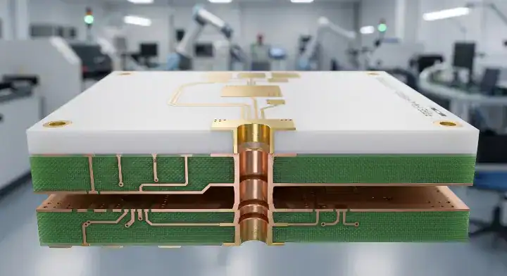
A hybrid RF/digital board needs an approved bonding construction; there is no basis here for declaring FEP mandatory for every mmWave77-to-FR4 build.
Place the RF transmission structure and its return plane deliberately. The layers beneath that plane still matter to mechanical behavior, vias and lamination, even if the plane substantially separates the RF field from the digital layers. The stackup drawing should name the core, bonding material, copper and dielectric dimensions rather than saying only “PTFE plus high-Tg FR4.”
Bonding options are material-system specific. As a counterexample to a universal FEP-only rule, Rogers offers a 2929 hydrocarbon bondply intended for multilayer constructions that include specified PTFE composite families. That document does not establish compatibility with mmWave77. The proposed mmWave77 bonding system still needs confirmation from the laminate supplier and fabricator.
Ask for the approved press cycle, surface preparation, storage conditions and the process limits of every material in the stack. FR4 glass-transition temperature alone does not authorize an arbitrary lamination temperature. The board fabricator must account for the complete thermal history and verify the resulting bond quality using the agreed inspection and qualification methods.
Review copper distribution and mechanical support along with the materials. Where the stack is asymmetric, request the fabricator’s assessment of bow, twist and dimensional movement for the specific panel. A balanced-looking diagram is not a substitute for the dimensions and tolerances needed by the assembly line.
Review fabrication records for the proposed material
Confirm a documented process for mmWave77 rather than assuming every PTFE laminate uses identical drill parameters, surface treatment or scaling factors.
Drilling, hole preparation, metallization, imaging and lamination should be considered as a connected process. The relevant question is whether the selected route produces acceptable holes and conductors on the ordered construction. Ownership of one named treatment machine does not alone establish that capability, and outsourcing a qualified operation does not automatically make a supplier unsuitable.
Request a sample cross-section from a representative build when plated holes are part of the design. Its value depends on the drilled structure, preparation process, plating and acceptance criteria matching the proposed order. An attractive photograph without a sample identifier or scale cannot establish hole-wall integrity or copper thickness.
For the RF pattern, agree how finished line width and conductor shape are measured. Tie inspection locations to the narrow or phase-sensitive features on the artwork. A general optical-inspection statement does not explain whether those particular features are controlled across the panel.
Process changes also need a defined boundary. The approved material, foil, bonding film and fabrication site should not be silently replaced during a repeat order. Decide which changes require notification and which require a new comparison build. The related RO3003 processing discussion can provide context for a separate PTFE product, but its process settings should not be copied into a mmWave77 work instruction without validation.
Keep automotive approval separate from material identity
An automotive radar application needs the program’s component, board and system approvals. A laminate name or a manufacturer’s management-system certificate does not itself approve a finished radar sensor.
Shengyi lists automotive radar among the mmWave77 application areas. That supports considering the material for this use; it does not establish adoption by a named automaker or certify every proposed stackup. Claims about a particular OEM, field population or savings project need a traceable public announcement or an authorized project record.
For a material change, identify the customer-approved part or construction being changed, the reason for the change and the tests affected. Have the responsible design and quality teams determine the required qualification. Do not invent a universal requalification cost, duration or sample count: those depend on the program and the extent of the change.
Keep certificate scope readable. A quality-management certificate concerns the organization and scope shown on that certificate. Material test reports, safety recognition, restricted-substance documents and functional-safety activities answer different questions. A purchasing file is more useful when each document is linked to the requirement it actually addresses.
An unresolved automotive approval should be visible before production quantities are ordered. A supplier may be able to make evaluation boards while the end customer is still reviewing a substitution, but those boards should retain their evaluation status and construction identification. Passing an early RF test is one input to approval rather than permission to bypass the program’s remaining requirements.
Compare the cost of accepted boards
Obtain quotations for the same deliverable and compare the engineering work as well as the material invoice. No verified price comparison here supports a fixed percentage saving for mmWave77.
Separate material availability, fabrication setup, test coupons, inspection, assembly and qualification builds. A lower raw-panel price can be offset by a different panel yield, additional characterization or a change in minimum order. Conversely, a suitable material with a stable local supply can be worth evaluating even when its nominal performance resembles the approved option.
Use an explicit cost model: total program cost equals setup and validation charges plus the cost of the accepted board quantities and any identified logistics or rework charges. Put actual supplier quotations into that model. Do not count speculative reductions in warranty failures as guaranteed savings, and do not compare one quote that includes RF coupons with another that excludes them.
Frequency alone also does not decide whether the material is excessive. Lower-frequency designs may still have demanding loss, electrical-length, environmental or physical-size requirements. Evaluate the candidate against those requirements and the available alternatives. A “below this frequency, always downgrade” rule hides precisely the trade-offs that the procurement comparison should expose.
Prepare the radar build for quotation
Submit enough information to quote the intended construction and its validation, including any details that remain open. A material name without a stackup leaves too much of the RF design to assumption.
- Identify the mmWave77 core and copper option, or flag the material detail that still needs confirmation.
- Supply the stackup, RF artwork, operating band and dimensional tolerances that affect the antenna or feed lines.
- Describe the intended bonding system, plated structures and assembly thermal history.
- Attach the coupon drawing, measurement reference planes and acceptance limits for the comparison build.
- State whether the order is for evaluation or an already approved production construction.
For an evaluation quotation, send the existing radar stackup and the proposed substitution to QueenEMS, together with the comparison measurements you need. This allows the fabrication and test scope to be discussed before a material saving is treated as a program decision.
FAQ
Can the existing antenna artwork remain unchanged?
It can be retained for a controlled comparison build. Whether it can remain unchanged in production depends on the measured results and the approved requirements; equal nominal process Dk values do not settle that question.
Is 0.0010 the guaranteed loss tangent at 77 GHz?
No. The cited Shengyi table states 10 GHz/23°C for that typical value. Obtain operating-band characterization or measure an appropriate reference circuit before assigning a loss model at another frequency.
Does a ceramic-filled PTFE board behave like solid AlN?
No. These are different substrate systems with different fabrication and material properties. Use the ceramic substrate overview when the design question is about solid ceramic circuits rather than a filled RF laminate.
Written by the QueenEMS Engineering Team
Upload your files today · Free DFM check before production · Ship worldwide
Get your PCB prototypes in as fast as 24 hours. We handle FR4, Rogers, and Flex up to 60 layers — free prototypes for 2–4 layer boards, no minimum order.
Just upload your Gerber + BOM — we source every part, assemble, and inspect (AOI + X‑Ray) so you don't have to chase suppliers. Boards ship in as fast as 24 hours.