
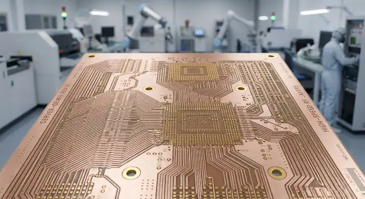
Quick Answer: I-Speed is a low-loss multifunctional epoxy PCB laminate featuring a stable Dk of 3.63 and a Df of 0.0060 at 10 GHz. It operates as the perfect bridge material, cutting substrate costs by up to 30% for 10G-25G NRZ and PCIe Gen4 applications when standard high-Tg FR-4 fails signal integrity tests. Key takeaways:
For a broader comparison of laminate families, electrical properties, processing limits, and sourcing choices, see our PCB materials guide.
- Delivers -0.82 dB/inch insertion loss on typical 10G Ethernet channels.
- Requires absolutely zero process modifications from standard 190°C FR-4 pressing.
- Completes the manufacturer’s six-tier material pyramid as a Tier 5 solution.
- Available in a specialized CAF version for fine-pitch BGAs under 0.65 mm.
Table of Contents
- What Is I-Speed and Where Does It Fit in Isola’s High-Speed Lineup?
- How Does This Material Compare to Its CAF-Enhanced Version?
- How Does the Core Substrate Complete Isola’s Six-Tier Pyramid?
- What Electrical and Thermal Properties Define I-Speed?
- When Is FR408HR Not Enough but I-Tera MT40 Overkill?
- How Does I-Speed Compare to Megtron 4, EM-528, and S7439?
- What Stackup Strategies Work Best with Hybrid Builds?
- Why Is It the Easiest High-Speed Isola Material to Process?
- When Is This Epoxy Not Enough and What Are Halogen-Free Options?
- How Will Its Role Evolve as PCIe Gen5 Pushes Designs Higher?
- FAQ
Hardware engineers constantly battle insertion loss limits when routing long PCIe Gen4 or 10G Ethernet channels across high-density server boards. You might find that legacy materials fail your 18-inch trace budgets, forcing a panic upgrade to ultra-low-loss substrates that destroy your project’s profit margins. This exact scenario is where I-Speed enters the conversation, acting as a calculated cost-down substitute that preserves your signal integrity without paying for unused bandwidth margin.
What Is I-Speed and Where Does It Fit in Isola’s High-Speed Lineup?
I-Speed is a low-loss multifunctional epoxy laminate offering a precise dielectric constant of 3.63 and a dissipation factor of 0.0060 at 10 GHz. It specifically targets the middle ground in digital routing, serving designs that operate too fast for traditional FR-4 but do not require the extreme performance of premium PTFE or highly advanced thermoset resin systems.
Users on the Electronics Stack Exchange frequently ask: (1) “Is there a mid-tier laminate that bridges the gap between basic FR-4 and advanced RF materials?” Yes, this material fills that exact void, serving as the M4-M5 equivalent in the global supply chain.
Here is exactly what makes it fit perfectly into mid-tier server designs:
- The Df of 0.0060 provides a 35% reduction in signal loss compared to baseline high-Tg laminates.
- The resin system incorporates built-in UV blocking, which means standard automated optical inspection (AOI) equipment detects fluorescence flawlessly.
- Spread glass weave options are available to mitigate differential skew on tightly coupled differential pairs.
Key Takeaway: This substrate prevents you from overpaying for millimeter-wave grade materials on standard 10G-25G digital channels. Bottom line: Specify this material exclusively when your data rates sit firmly in the PCIe Gen3 to Gen4 territory.
| Feature | Specification | Target Application |
|---|---|---|
| Dk @ 10 GHz | 3.63 | 50-ohm microstrip / 100-ohm diff |
| Df @ 10 GHz | 0.0060 | 10G to 25G NRZ |
| Resin Base | Multifunctional Epoxy | Standard server boards |
Analysis: The 0.0060 dissipation factor hits the exact sweet spot for maintaining open eye diagrams at 16 Gbps speeds.
How Does This Material Compare to Its CAF-Enhanced Version?
The standard version utilizes a conventional fiberglass and resin matrix, while the CAF-enhanced version incorporates specially treated glass fibers to physically block conductive anodic filament growth. Both versions share identical electrical properties, including the 3.63 Dk and 0.0060 Df, but the enhanced iteration reduces the Z-axis coefficient of thermal expansion (CTE) from 45 ppm/°C down to 40 ppm/°C.
Engineers on the EEVBlog Forum often wonder: (2) “Do I need the CAF version for standard 0.8 mm pitch components?” No, the standard resin system easily passes standard reliability tests at that geometry.
Consider this engineering rule of thumb:
- Use the standard configuration for standard through-hole and 0.8 mm+ pitch BGA designs.
- Specify the enhanced version strictly for high-layer-count HDI boards utilizing fine-pitch BGAs (0.5 mm to 0.65 mm).
- The enhanced version typically carries a 10% to 15% price premium over the baseline material.
Key Takeaway: Upgrading to the CAF-resistant version alters the mechanical reliability in the Z-axis without changing your electromagnetic simulations. Bottom line: Always upgrade to the enhanced configuration when your pad-to-pad clearances drop below 0.65 mm in high-voltage environments.
| Metric | Standard Version | CAF-Enhanced Version |
|---|---|---|
| Z-CTE | ~45 ppm/°C | ~40 ppm/°C |
| Z-Expansion | ~2.8% | ~2.5% |
| Safe Pitch Limit | 0.7 mm to 0.8 mm | Verified at 0.5 mm |
Analysis: The 11% reduction in Z-axis expansion directly correlates to fewer microvia fractures during lead-free reflow cycles.
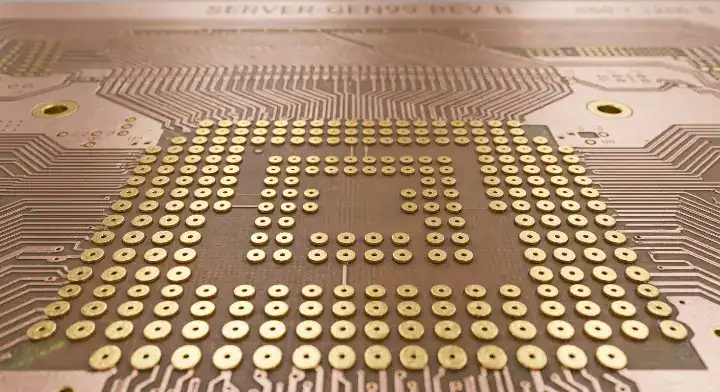
How Does the Core Substrate Complete Isola’s Six-Tier Pyramid?
This specific low-loss epoxy acts as the designated Tier 5 layer in the manufacturer’s lineup, completing a perfectly stepped portfolio of high-speed digital materials. It sits directly above the Tier 6 baseline materials and just below the Tier 4 mid-loss thermoset resins, creating a logical progression path for signal integrity engineers scaling their designs.
With this addition, the high-speed portfolio forms a complete six-tier pyramid where every tier has a clear, uncompromised role. The baseline handles the power and ground base. This Tier 5 epoxy handles the 10G-25G middle ground that lower tiers cannot reach but higher tiers overserve. Moving up, the Tier 4 covers PCIe Gen5. The next step is detailed in the Isola Tachyon 100G ultra-low-loss laminate guide, which handles 56-112G PAM4. Finally, Tier 1 handles RF/mmWave up to 110 GHz. The practical value is massive: a fabrication facility qualified on any one product can qualify the rest within a single engineering lot, because the press recipes, desmear cycles, and handling procedures remain strictly consistent across the entire family.
Key Takeaway: The matched material ecosystem allows you to mix and match prepregs and cores without risking catastrophic delamination. Bottom line: Standardize your supply chain on this six-tier pyramid to drastically reduce factory qualification times for new product introductions.
| Tier Level | Designated Material | Primary Speed Target |
|---|---|---|
| Tier 6 (Base) | Baseline High-Tg | Power / Ground / < 5 Gbps |
| Tier 5 (Current) | I-Speed | PCIe Gen4 / 10G-25G |
| Tier 3 (Premium) | Tachyon 100G | 56G-112G PAM4 |
Analysis: Maintaining consistent factory chemistry across different speed grades eliminates the need for expensive pilot runs when upgrading your board’s data rates.
What Electrical and Thermal Properties Define I-Speed?
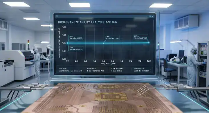
The material delivers an exceptionally flat Dk response, shifting imperceptibly from 3.65 at 1 GHz to exactly 3.63 at 10 GHz. Thermal stability is anchored by a glass transition temperature (Tg) of 180°C and a decomposition temperature (Td) of 360°C, resulting in a substrate that easily survives six consecutive lead-free reflow cycles at 260°C.
Z-axis expansion is a critical metric measuring how much the material swells under heat. The Z-expansion rests at approximately 2.8% from 50°C to 260°C, which prevents plated through-hole (PTH) copper barrel cracking during heavy thermal shock testing.
Here is why these numbers matter:
- The flat Dk profile across frequencies minimizes phase distortion on wideband digital signals.
- The 180°C Tg guarantees the board will not soften or warp inside poorly ventilated server chassis environments.
- The 360°C Td provides a massive thermal safety buffer during complex sequential lamination pressing.
Key Takeaway: The combination of low loss and high thermal mass makes this epoxy perfectly suited for thick, high-layer-count backplanes. Bottom line: You can confidently specify this material for 24-layer server boards knowing the vias will survive heavy assembly cycles.
| Thermal Property | Value | Factory Impact |
|---|---|---|
| Tg (DSC) | 180°C | Resists warpage |
| Td | 360°C | Survives multiple laminations |
| Lead-Free Reflow | 6 cycles @ 260°C | Excellent assembly yield |
Analysis: A 360°C decomposition temperature is mandatory for thick server boards that require extended pre-heating during wave soldering.
When Is FR408HR Not Enough but I-Tera MT40 Overkill?
You must upgrade from the baseline when your 10G Ethernet traces exceed 15 inches, causing the 0.0092 Df to consume your entire insertion loss budget. Conversely, paying double the price for a 0.0031 Df material becomes financial waste when your PCIe Gen4 channels already display wide-open eye diagrams on a 0.0060 Df substrate.
A customer came to us with a 16-layer server management board running 10G Ethernet and PCIe Gen4. The original design used high-Tg FR408HR material specifications throughout. At 18-inch trace lengths, the 10G channels measured 1.05 dB/inch insertion loss at 6.25 GHz — totaling 18.9 dB, just barely within the strict 20 dB budget. The customer asked whether upgrading all signal layers to the advanced I-Tera MT40 PCB laminate for Gen5 would help. We proposed the Tier 5 epoxy instead: insertion loss dropped to 0.82 dB/inch — totaling 14.8 dB, granting 5.2 dB of comfortable margin. The Tier 4 alternative would have delivered 0.65 dB/inch, yielding more margin than electrically necessary. Material cost on the Tier 5 epoxy ran approximately 30% below the Tier 4 option. The customer saved $85 per panel across 50 panels, equaling $4,250 on the first lot alone, with margin to spare. That $4,250 was pure waste avoided, as the extra Tier 4 margin would have sat entirely unused.
Key Takeaway: Bridging the gap with a 0.0060 Df material maximizes your signal integrity budget without inflating the bill of materials. Bottom line: Always simulate your trace lengths on the Tier 5 epoxy before blindly approving purchase orders for Tier 4 thermoset materials.
| Signal Type | Tier 6 (Df 0.0092) | Tier 5 (Df 0.0060) | Tier 4 (Df 0.0031) |
|---|---|---|---|
| PCIe Gen3 (8G) | Passes | Passes | Overkill |
| PCIe Gen4 (16G) | Fails at >15 inch | Sweet Spot | Overkill |
| 25G NRZ | Fails | Passes at <10 inch | Required at >12 inch |
Analysis: The decision boundary is defined entirely by trace length; a 25G signal can survive on Tier 5 epoxy only if the routing distance remains extremely short.
How Does I-Speed Compare to Megtron 4, EM-528, and S7439?
This low-loss epoxy competes directly in the M4-M5 performance class, providing a 0.0060 Df that closely matches the 0.005 Df of the Panasonic Megtron 4 equivalent material. While Taiwanese and Chinese manufacturers offer competing M4-grade laminates like EM-528 and S7439, this specific resin system maintains a distinct advantage in Western supply chain availability and ecosystem compatibility.
Reddit’s r/PrintedCircuitBoard users frequently ask: (3) “How does this North American epoxy compare to popular Asian M4 laminates?” The electrical performance is virtually indistinguishable, which means the deciding factor is your factory’s location and their preferred prepreg ecosystem.
Before finalizing your BOM, evaluate these market realities:
- The Dk of 3.63 is slightly lower than EM-528’s 3.9, requiring minor trace width adjustments if migrating a layout.
- Pricing sits comfortably at 2-3x the cost of standard FR-4, aligning perfectly with global M4 market rates.
- You can utilize a comprehensive high-speed PCB material selector tool to verify lead times in your specific manufacturing region.
Key Takeaway: The core advantage lies not in raw specs, but in the material’s seamless integration with other layers in the same manufacturer’s ecosystem. Bottom line: Choose this epoxy over Megtron 4 when your stackup already utilizes other materials from the same brand’s six-tier pyramid.
| Laminate Brand | Dk @ 10 GHz | Df @ 10 GHz | Halogen-Free |
|---|---|---|---|
| I-Speed | 3.63 | 0.0060 | No |
| Megtron 4 | 3.80 | 0.0050 | No |
| EM-528 | 3.90 | 0.0060 | Yes |
Analysis: While EM-528 offers halogen-free compliance natively, the standard M4 materials provide a more established history of processing reliability.
What Stackup Strategies Work Best with Hybrid Builds?
A hybrid stackup strategy leverages this 0.0060 Df epoxy strictly on the outer high-speed signal layers while utilizing significantly cheaper 0.0092 Df materials for the internal power and ground planes. This technique reduces overall bare board costs by up to 25% compared to homogeneous constructions, because you only pay for premium low-loss chemistry where the millimeter-wave fields actually propagate.
To execute this correctly, your factory must maintain strict thermal profiling.
Follow these non-negotiable hybrid rules:
- Always pair materials that possess identical 180°C glass transition temperatures to prevent asymmetric cooling stress.
- Ensure the prepreg used for bonding belongs to the higher-performing resin system to maintain signal integrity through the vias.
- Partner with a facility that demonstrates proven multilayer PCB manufacturing capabilities to guarantee perfect registration during the pressing cycle.
Key Takeaway: Strategic layer assignment protects your budget without sacrificing a single decibel of insertion loss on critical data lines. Bottom line: Never build a 16-layer homogeneous low-loss board when 8 of those layers are simply carrying DC power.
| Layer Type | Recommended Material | Justification |
|---|---|---|
| High-Speed Signal | Tier 5 Low-Loss Epoxy | Minimizes attenuation |
| DC Power Plane | Tier 6 High-Tg Base | Slashes material costs |
| Ground Plane | Tier 6 High-Tg Base | Slashes material costs |
Analysis: Hybrid pressing relies entirely on matched resin curing temperatures; mixing incompatible chemistry families will result in catastrophic delamination during reflow.
Why Is It the Easiest High-Speed Isola Material to Process?
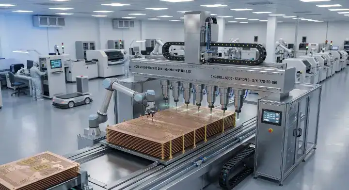
This epoxy system eliminates the need for expensive plasma desmear or specialty drill bits because its resin chemistry directly mimics standard high-Tg FR-4. The factory floor operators do not need to adjust their chipload settings, alter their permanganate bath concentrations, or recalibrate their lamination press profiles when this material hits the production line.
This specific material is the easiest high-speed laminate we process — even easier than the baseline Tier 6. The manufacturer’s own documentation describes it as “the closest to conventional FR-4 processing of all high-speed digital materials,” and our production data confirms this fact. Drill parameters run at standard FR-4 chipload with zero reduction needed. Drill bit life averages 2,800 hits — identical to standard high-Tg FR-4 and remarkably better than the Tier 6 baseline (2,600) or the advanced Tier 4 (2,200). The lamination cycle is standard FR-4: 190°C for 60 minutes. Desmear utilizes standard permanganate with no chemical enhancement needed. The built-in UV blocking and AOI fluorescence mean our inspection equipment requires zero adjustment from basic settings. First-pass yield on our last 120 panels averaged 97.4% — statistically indistinguishable from our standard FR-4 yield. If a fab currently runs FR-4, this material requires literally no process change.
Key Takeaway: The standard processing parameters completely eliminate the costly NRE (Non-Recurring Engineering) fees typically associated with high-frequency RF boards. Bottom line: You get high-speed digital performance while paying standard FR-4 fabrication labor rates.
| Fabrication Step | Processing Requirement | Comparison to FR-4 |
|---|---|---|
| Drilling | Standard chipload | Identical (2,800 hits/bit) |
| Desmear | Standard permanganate | Identical |
| Lamination | 190°C for 60 mins | Identical |
Analysis: Factory yields directly dictate your unit price; a material that behaves exactly like standard FR-4 guarantees minimal scrap and highly predictable lead times.
When Is This Epoxy Not Enough and What Are Halogen-Free Options?
You must immediately abandon this material when your corporate environmental directives mandate strict halogen-free compliance for consumer electronics or European server deployments. The standard resin contains brominated flame retardants to achieve its UL 94 V-0 flammability rating, rendering it unsuitable for “green” manufacturing initiatives.
Users on the SierraConnect forum frequently ask: (4) “What is the direct halogen-free equivalent to this 0.0060 Df epoxy?” You must step laterally into a different resin family, typically requiring a move up to the TerraGreen series.
Prepare for these specific manufacturing shifts:
- Halogen-free resins are inherently more brittle, requiring a 15% reduction in drill feed rates to prevent hole wall tear-out.
- The pressing cycle demands tighter temperature controls to achieve proper resin flow.
- Reviewing halogen-free PCB manufacturing rules is mandatory before sending your Gerbers to the factory.
Key Takeaway: Environmental compliance forces a resin chemistry change that slightly impacts both material cost and mechanical fabrication speeds. Bottom line: Never attempt to pass this standard epoxy through a halogen-free audit; specify the TerraGreen alternative from day one.
| Requirement | Standard Epoxy | Halogen-Free Alternative |
|---|---|---|
| Flame Retardant | Brominated | Phosphorus-based |
| Eco-Compliance | Standard RoHS | RoHS + Halogen-Free |
| Drill Feed Rate | 100% baseline | 85% of baseline |
Analysis: Phosphorus-based flame retardants harden the resin matrix, directly forcing factories to replace drill bits more frequently to maintain hole wall quality.
How Will Its Role Evolve as PCIe Gen5 Pushes Designs Higher?
As server architectures transition aggressively toward 32 Gbps PCIe Gen5, the 0.0060 Df of this epoxy will restrict channel lengths to extremely short runs, typically under 3 to 4 inches. While it cannot serve as the main backplane material for next-generation platforms, it will continue to dominate peripheral routing, riser cards, and legacy 10G interface modules where its cost-to-performance ratio remains unbeatable.
The industry is adopting a highly localized material strategy to combat insertion loss.
Here is how design teams are adapting:
- Utilizing ultra-low-loss materials strictly for the primary CPU-to-GPU Gen5 highways.
- Deploying this mid-tier epoxy for the dense PCIe Gen4 NVMe storage arrays on the same motherboard.
- Shifting entirely to hybrid stackups to balance the skyrocketing costs of next-generation copper cladding.
Key Takeaway: This material will not drive the Gen5 revolution, but it will remain the economic backbone supporting the secondary circuits on Gen5 boards. Bottom line: Continue specifying this laminate for any digital channel operating at or below 16 Gbps, regardless of the board’s primary processor speed.
| Protocol | Max Viable Trace Length on 0.0060 Df | Future Outlook |
|---|---|---|
| 10G Ethernet | > 18 inches | Remains dominant choice |
| PCIe Gen4 | ~ 12-15 inches | Sweet spot application |
| PCIe Gen5 | < 4 inches | Restricted to short risers |
Analysis: The physics of 32 Gbps attenuation force engineers to partition their boards, applying premium materials only where the high-frequency math demands it.
FAQ
Can I use this low-loss epoxy instead of premium thermosets for server boards? Yes, you can confidently downgrade to this material if your server architecture is limited to PCIe Gen4 or 10G-25G NRZ protocols. It delivers a 0.0060 Df that perfectly supports 16 Gbps speeds, saving you 30% in material costs compared to ultra-low-loss Gen5 laminates.
What makes this substrate better than standard FR408HR for long traces? The 35% reduction in dissipation factor (0.0060 vs 0.0092) is the primary advantage. This significantly lower attenuation allows you to route 10G Ethernet channels beyond 15 inches without violating your total insertion loss budget, which is impossible on baseline high-Tg FR-4.
How do I know if my design requires the CAF-enhanced version? Check your BGA pitch and trace-to-trace clearances. If you are designing high-layer-count HDI boards with fine-pitch components down to 0.5 mm, the CAF version provides the enhanced Z-axis stability required to prevent conductive anodic filament shorts.
Is it safe to substitute Megtron 4 with this specific material? Yes, both materials occupy the exact same M4-M5 performance tier with nearly identical electrical specifications. The choice ultimately depends on whether your fabrication partner favors the North American Isola prepreg ecosystem or the Asian Panasonic supply chain.
Does this material require specialized high-frequency pressing cycles? No, it processes exactly like standard conventional FR-4. Your fabricator will use their standard 190°C lamination press cycle, standard permanganate desmear, and standard drill speeds, resulting in incredibly high first-pass yields.
Conclusion
Navigating the material selection for 10G to 25G digital architectures requires a precise balance between signal integrity margin and raw board cost. The I-Speed laminate serves as the perfect engineering bridge, offering the 0.0060 Df necessary to sustain PCIe Gen4 channels while completely avoiding the financial premiums and processing complexities of premium RF thermosets. By leveraging this Tier 5 epoxy in a well-planned hybrid stackup, you protect your insertion loss budgets and maintain access to standard FR-4 manufacturing lines worldwide. If you need engineering assistance simulating trace attenuation or designing a cost-effective hybrid stackup for your next server board, contact us today for high-speed PCB fabrication.
Written by the QueenEMS Engineering Team.
Upload your files today · Free DFM check before production · Ship worldwide
Get your PCB prototypes in as fast as 24 hours. We handle FR4, Rogers, and Flex up to 60 layers — free prototypes for 2–4 layer boards, no minimum order.
Just upload your Gerber + BOM — we source every part, assemble, and inspect (AOI + X‑Ray) so you don't have to chase suppliers. Boards ship in as fast as 24 hours.