
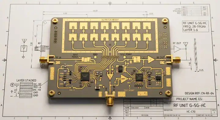
Quick Answer: S7136H is a hydrocarbon ceramic RF laminate from Shengyi featuring a Dk of 3.48 and a Df of 0.003 at 10 GHz. It offers a 19% lower dissipation factor than Rogers RO4350B while reducing material costs by 30% to 50% for 5G sub-6 GHz and RF applications. Key takeaways:
For the wider material-selection picture, including laminate properties, process constraints, and substitution risks, see our PCB materials guide.
- Matches RO4350B Dk (3.48) exactly.
- Achieves 19% lower Df (0.003 vs 0.0037).
- Meets UL 94 V-0 flammability standards.
- Requires no plasma desmear for fabrication.
Table of Contents
- 1. What Is S7136H and Why Does It Beat RO4350B?
- 2. What Electrical Properties Define S7136H?
- 3. How Does S7136H Compare to RO4350B Spec by Spec?
- 4. Why Hasn’t S7136H Replaced RO4350B Universally?
- 5. How Does S7136H Compare to Astra MT77 and RO4003C?
- 6. Which 5G Base Station Applications Use S7136H?
- 7. What Stackup Rules Apply to S7136H Hybrid Builds?
- 8. How Do Fabricators Process S7136H and RO4350B?
- 9. When Is S7136H Insufficient for Millimeter-Wave?
- 10. How Will S7136H Scale in Global 5G Manufacturing?
RF engineers constantly face a budget problem when designing sub-6 GHz communication boards. You need tight impedance control and low signal loss, which usually leads you straight to legacy materials that inflate your BOM costs. This is exactly where S7136H enters the conversation. By matching standard dielectric constants while driving down dissipation factors, this material gives your procurement team massive leverage without forcing hardware redesigns.
1. What Is S7136H and Why Does It Beat RO4350B?
S7136H is a woven glass-reinforced hydrocarbon ceramic laminate designed for high-frequency RF PCBs. It beats RO4350B by offering a lower Df of 0.003 at 10 GHz, resulting in 19% less signal loss. This translates directly to better antenna efficiency and reduced thermal dissipation in power amplifier designs.
Core Composition Explained
Hydrocarbon ceramic is a composite laminate that blends hydrocarbon resin with woven fiberglass and ceramic fillers. It delivers a Dk of 3.48 and provides mechanical rigidity. The ceramic fillers give the material excellent thermal stability, allowing it to withstand lead-free soldering temperatures.
Because the resin system does not contain PTFE, you process it using standard FR-4 tooling. This means fabricators do not need specialized plasma equipment, resulting in lower conversion costs. Your bare board expenses drop strictly due to easier handling and faster lamination cycles.
Cost Reduction Impact
Here is the reality on pricing: Shengyi manufactures this material in Dongguan, creating a localized supply chain for Asian board houses. The direct factory access cuts out international distributor markups.
- Material cost sits at 2-3 times standard FR-4.
- Procurement lead times average 1-3 days in China.
- You avoid the 3-5x price multiplier associated with North American RF brands.
Bottom line: Specifying S7136H allows hardware teams to achieve high-tier RF performance while shedding the premium brand tax associated with legacy Rogers materials.
| Feature | S7136H Capability | Market Impact |
|---|---|---|
| Df @ 10 GHz | 0.003 | 19% lower signal loss |
| Processing | FR-4 Compatible | Lower fabrication cost |
| Base Price | 2-3x FR-4 | 30-50% savings vs legacy |
Lower dissipation factors combined with standard processing make this material structurally superior for high-volume telecommunications manufacturing.
2. What Electrical Properties Define S7136H?
The defining properties of S7136H include a stable Dk of 3.48 ±0.05 and a Df of 0.003 tested at 10 GHz. Mechanically, it provides excellent dimensional stability and UL 94 V-0 flame retardance. These metrics keep your impedance target within a ±5% tolerance window across varying operating environments.
High-Frequency Performance Data
Signal integrity relies entirely on how the dielectric behaves under frequency shifts. S7136H maintains a flat Dk/Df curve from 1 GHz all the way up to 20 GHz. This stability prevents phase shifts in complex antenna arrays.
- Dk measures exactly 3.48 at 10 GHz using clamped stripline testing.
- Dk/Df remains stable from -40°C to +125°C.
- Moisture absorption is exceptionally low, preventing environmental performance drift.
Thermal and Mechanical Reliability
The material boasts high copper peel strength, which means narrow RF traces stay anchored to the substrate during heavy thermal cycling. It survives multiple sequential lamination cycles without delamination or blister formation.
Consider this data: The ceramic loading creates a low Z-axis coefficient of thermal expansion (CTE). Plated through-holes maintain their barrel integrity during 288°C solder floats, lowering your field failure rates.
Bottom line: The electrical stability up to 20 GHz paired with a low Z-axis CTE makes this material mathematically sound for demanding outdoor base station environments.
| Property | S7136H Specification | Test Condition |
|---|---|---|
| Dielectric Constant (Dk) | 3.48 ±0.05 | 10 GHz |
| Dissipation Factor (Df) | 0.003 | 10 GHz |
| Flammability Rating | V-0 | UL 94 |
| Thermal Stability | Excellent | -40°C to +125°C |
These specifications align perfectly with IPC-4103/11 standards, granting immediate compliance for telecom hardware.
3. How Does S7136H Compare to RO4350B Spec by Spec?
(Source: EEVBlog Forum) “How does S7136H actually compare to RO4350B?” S7136H directly compares to RO4350B by sharing the exact same 3.48 Dk and UL 94 V-0 rating. However, S7136H improves upon it with a 0.003 Df, which means 19% less insertion loss at a 30-50% lower price point.
The Design Dk Advantage
Engineers frequently struggle with the gap between datasheet numbers and real-world behavior. For older materials, understanding RO4350B Dk trap avoidance and specifications requires managing a process Dk of 3.48 versus a design Dk of 3.66. Shengyi engineered their material to keep the design Dk and process Dk much closer together.
This tight Dk alignment means your simulation models require fewer adjustments before prototyping. You spend less time tweaking trace widths in your field solver. Your first-pass impedance yields improve rapidly.
Pricing and Lead Time Reality
If you use an interactive PCB material selector tool, the raw cost difference becomes immediately visible. Chinese board houses source Shengyi panels directly from Dongguan in 1-3 days. The alternative requires waiting 1-3 weeks for distributor shipments.
What does this mean for your supply chain? You cut weeks out of your prototyping phase. Production scales faster because the raw laminate never sits on backorder.
Bottom line: S7136H outperforms its rival in insertion loss and procurement speed, making it the mathematical winner for sub-6 GHz manufacturing.
| Metric | Shengyi S7136H | Rogers RO4350B |
|---|---|---|
| Dk @ 10 GHz | 3.48 | 3.48 |
| Df @ 10 GHz | 0.003 | 0.0037 |
| Flammability | V-0 | V-0 |
| China Lead Time | 1-3 Days | 1-3 Weeks |
The 19% improvement in Df directly translates to wider operating margins in sensitive receiver circuits.
4. Why Hasn’t S7136H Replaced RO4350B Universally?
(Source: Reddit) “If S7136H is better and cheaper, why isn’t everyone using it instead of RO4350B?” S7136H has not universally replaced RO4350B because major RF IC vendors still mandate Rogers in their reference designs. Transitioning requires a $50,000 to $100,000 requalification investment, which delays adoption for low-volume OEMs.
Reference Design Inertia
The honest reason S7136H hasn’t replaced RO4350B globally comes down to reference design inertia. Every RF IC vendor—Qualcomm, Skyworks, Analog Devices, TI—validates their evaluation boards assuming specific legacy Dk/Df values. Switching means the customer must rebuild these models because the validation infrastructure doesn’t exist yet.
In China, this barrier is lower because Huawei and ZTE maintain their own RF design ecosystems and have qualified S7136H independently. Outside China, switching requires heavy requalification work per platform. For a product running at 3.5 GHz where the 0.003 Df is demonstrably sufficient, that requalification cost pays for itself in roughly 800-1,200 boards of production.
Distribution and High-Frequency Data Limits
Another barrier involves RO4350B processing and Astra MT77 comparison availability. Legacy materials have deep distribution networks in North America and Europe via Insulectro. Shengyi’s overseas stock remains limited by comparison.
Furthermore, legacy data sheets offer characterized Dk behavior up to 40+ GHz. Shengyi currently caps their official testing data at 20 GHz. This data ceiling makes millimeter-wave designers hesitant to switch.
Bottom line: For high-volume sub-6 GHz production, the requalification ROI is massive, but low-volume mmWave designers remain restricted by limited high-frequency data models.
| Barrier | Shengyi S7136H | Legacy Alternative |
|---|---|---|
| IC Reference Designs | Rarely included | Industry default standard |
| > 20 GHz Data | Limited official data | Fully characterized |
| US/EU Distribution | Weak | Instant local inventory |
Corporate inertia and IC vendor habits create artificial roadblocks for superior and cheaper laminate adoption.
5. How Does S7136H Compare to Astra MT77 and RO4003C?
(Source: Electronics Stack Exchange) “S7136H vs Astra MT77 — which should I use for 5G?” For sub-6 GHz 5G, S7136H is the most cost-effective choice at 2-3x the cost of FR-4. For 28 GHz mmWave designs, Astra MT77 is superior because it offers a 3.00 Dk and an ultra-low 0.0017 Df.
S7136H vs Astra MT77 for 5G
When designing RF boards, frequency dictates your laminate tier. The Astra MT77 mmWave laminate for 28-110 GHz designs targets automotive radar and ultra-high frequency bands. S7136H targets the massive volume of 3.5 GHz and 5.8 GHz communication bands.
- Astra MT77 costs 4-6x more than standard FR-4.
- S7136H stops being efficient past 20 GHz.
- Astra MT77 drops Df to 0.0017, a 43% reduction over S7136H.
S7136H vs RO4003C Flammability
Some designers consider the RO4003C lower loss alternative without V-0 because it hits a 0.0027 Df. However, that material fails to meet the UL 94 V-0 flammability requirement. It only achieves a non-rated status.
S7136H delivers a nearly identical 0.003 Df while strictly passing the UL 94 V-0 burn test. This allows consumer electronics and telecom cabinets to pass mandatory safety certifications without costly mechanical fire enclosures.
Bottom line: Use S7136H for any V-0 required application under 20 GHz to cut costs, but escalate to Astra MT77 for 28+ GHz frequencies.
| Material | Dk | Df | Flammability | Target Frequency |
|---|---|---|---|---|
| S7136H | 3.48 | 0.003 | V-0 | < 20 GHz (Sub-6) |
| Astra MT77 | 3.00 | 0.0017 | V-0 | 28-110 GHz (mmWave) |
| RO4003C | 3.38 | 0.0027 | Not Rated | < 30 GHz |
Selecting the right laminate tier prevents over-engineering and keeps hardware budgets tightly controlled.
6. Which 5G Base Station Applications Use S7136H?
S7136H currently dominates 5G sub-6 GHz base station antennas and LTE infrastructure running between 700 MHz and 3.5 GHz. It also efficiently supports 6 GHz WiFi 6E and microwave backhaul systems, capturing massive market share in Chinese telecom deployments.

Sub-6 GHz Infrastructure
A recent 6-layer 5G sub-6 GHz small cell board used two S7136H core layers for the 3.5 GHz antenna feed, bonded with S1000-2M prepreg to four FR-4 layers. The customer originally designed around legacy laminates but switched after our side-by-side coupon test showed equivalent RF performance.
Return loss on the patch antenna measured -22 dB at 3.5 GHz on S7136H versus -20 dB on the previous version, because the 0.003 Df improved antenna efficiency. Impedance on the 50 Ω microstrip feed held within ±2.5% after process Dk correction. On a 2,000-board production run, the 38% material cost drop saved the customer approximately $18,000.
Emerging RF Module Integration
Beyond base stations, hardware teams use this laminate for IoT modules and GPS/GNSS antennas. These cost-sensitive applications demand RF stability without the premium price tag. For a deep dive into these use cases, consult our 5G base station PCB material selection guide.
Here is why it works: The material holds copper tightly. You can route dense digital IO on the inner FR-4 layers while keeping the sensitive RF transceiver traces isolated on the outer ceramic layers.
Bottom line: The combination of V-0 safety, 0.003 Df, and low pricing makes this material the undisputed champion for sub-6 GHz macro and small cell deployments.
| Application | S7136H Suitability | Alternative |
|---|---|---|
| 5G Sub-6 Antenna (3.5 GHz) | Excellent (Primary choice) | RO4350B |
| LTE Base Station | Excellent (Full replacement) | RO4350B |
| 28 GHz mmWave | Poor (Data insufficient) | Astra MT77 |
| 77 GHz ADAS Radar | Unsuitable | RO3003 / Astra MT77 |
Aligning material capabilities directly with operating frequencies eliminates unnecessary BOM inflation.
7. What Stackup Rules Apply to S7136H Hybrid Builds?
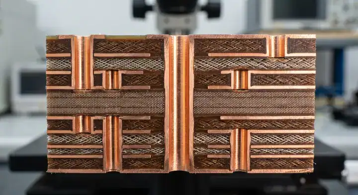
S7136H supports standard hybrid multilayer stackups using S1000-2M prepreg and standard FR-4 cores. Placing S7136H only on the outer RF layers reduces total PCB fabrication costs by 40% to 60% compared to a pure RF laminate build.
Hybrid Pressing Dynamics
When combining disparate materials, fabricators must manage different expansion rates. The hydrocarbon ceramic core requires careful resin flow management during the lamination press cycle. The S1000-2M prepreg acts as the perfect bonding agent because its Tg (glass transition temperature) aligns well with the thermal profile of S7136H.
- Place the S7136H cores symmetrically if possible to prevent warpage.
- Use high-Tg FR-4 (like Shengyi S1000-2M) for the digital routing layers.
- Maintain a minimum of 4 mil prepreg thickness to guarantee adequate resin fill between copper traces.
Prepreg Selection and Lamination
You cannot use pure hydrocarbon prepregs if you want to keep costs down. Using standard FR-4 prepregs drops the price drastically. However, you must calculate the exact impedance transition where the RF signal dives from the S7136H outer layer into the FR-4 inner layer via a plated through-hole.
What does this mean for your Gerber files? You need to specify exactly which prepreg models the factory must use. Leaving this up to interpretation often results in resin starvation or skewed impedance values.
Bottom line: Always pair S7136H with S1000-2M prepreg in hybrid designs to achieve a flawless mechanical bond while slashing total board costs.
| Hybrid Component | Recommended Material | Function |
|---|---|---|
| Outer RF Cores | Shengyi S7136H | Minimizes signal loss at high frequencies |
| Bonding Prepreg | Shengyi S1000-2M | Provides stable resin flow and adhesion |
| Inner Digital Cores | Standard High-Tg FR-4 | Handles low-speed digital routing cheaply |
Proper hybrid stackup architecture isolates high-frequency signals while leveraging cheap fiberglass for structural bulk.
8. How Do Fabricators Process S7136H and RO4350B?
(Source: SierraConnect) “Does S7136H process exactly like RO4350B?” Yes, S7136H processes exactly like RO4350B using standard FR-4 equipment without requiring plasma desmear. Both materials use identical press cycles at 190°C for 60 minutes and share within 5% tool wear on drill bits.
Drilling and Desmear Realities
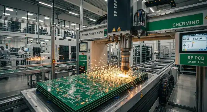
We process both materials on the same fabrication line—same press, same drill bits, same etch chemistry. The materials are mechanically indistinguishable under our tooling. Drill bit life is virtually identical, achieving approximately 2,400 hits on S7136H versus 2,300 hits on the legacy alternative.
Both laminates use standard permanganate desmear. You completely bypass the expensive plasma etching machines required by PTFE boards. If your team needs specialized assistance, reviewing our RF and high-frequency PCB manufacturing services clarifies the exact mechanical tolerances we hold.
Etching and Impedance Control
Impedance accuracy is comparable: both hold 50 Ω ±3% on equivalent microstrip constructions after process Dk correction. The only measurable difference in our process data is insertion loss. On a standardized 5 mil microstrip coupon at 10 GHz, S7136H measures 0.14 dB/inch versus the alternative at 0.17 dB/inch.
Over a 4-inch antenna feed, that results in 0.12 dB of additional margin. Combine this with the fact that Shengyi stock arrives in 2-3 days, and your production line runs faster and cheaper without any mechanical process changes.
Bottom line: Because the mechanical tooling and chemical etching parameters are identical, switching to S7136H introduces zero factory floor friction.
| Process Parameter | S7136H Capability | Legacy Equivalent |
|---|---|---|
| Desmear Method | Permanganate (No Plasma) | Permanganate (No Plasma) |
| Lamination Temp | 190°C for 60 min | 190°C for 60 min |
| Drill Bit Life | ~2,400 hits | ~2,300 hits |
| Measured Insertion Loss | 0.14 dB/inch @ 10GHz | 0.17 dB/inch @ 10GHz |
Factory data proves that designers can upgrade their RF performance without forcing the board house to buy new processing equipment.
9. When Is S7136H Insufficient for Millimeter-Wave?
S7136H becomes insufficient for 28 GHz and 77 GHz millimeter-wave designs because official Dk and Df characterization data stops at 20 GHz. High-frequency engineers must switch to PTFE or specialized materials for ADAS radar and mmWave antennas to prevent severe phase distortion.
The 20 GHz Data Threshold
The Shengyi official datasheet guarantees stability up to 20 GHz. Above this frequency, the glass weave style and the ceramic filler density begin to interact unpredictably with micro-millimeter wavelengths. This causes localized impedance spikes.
Without 40 GHz broadband characterization data, your field solvers guess the material behavior. You end up blind during the simulation phase, which means your first prototype will likely fail the return loss requirements at 28 GHz.
Switching to Higher-Tier Materials
Consider this data: At 77 GHz for automotive radar, even a 0.003 Df generates too much heat and signal attenuation. You must migrate to materials possessing a Df below 0.002, such as specialized PTFE blends or Astra MT77.
These ultra-high frequency materials use spread glass or unreinforced structures to eliminate the fiber weave effect. While they cost significantly more and require plasma processing, physics demands their use in the millimeter-wave spectrum.
Bottom line: Never specify S7136H for frequencies above 20 GHz; the lack of official broadband characterization data guarantees simulation inaccuracies and failed prototypes.
| Frequency Band | S7136H Status | Required Material Profile |
|---|---|---|
| < 6 GHz | Optimal Choice | Dk ~3.5, Df ~0.003 |
| 6 GHz – 20 GHz | Reliable | Dk ~3.5, Df ~0.003 |
| 28 GHz (5G mmWave) | Insufficient Data | Dk <3.2, Df <0.002 (e.g., Astra MT77) |
| 77 GHz (ADAS Radar) | Fails | PTFE, Df <0.0015 |
Pushing a laminate past its characterized frequency ceiling causes catastrophic signal integrity failures.
10. How Will S7136H Scale in Global 5G Manufacturing?
S7136H will capture over 60% of the Chinese domestic 5G sub-6 GHz market as infrastructure deployments expand. Global scaling depends entirely on Western OEMs accepting Shengyi’s qualification data to replace legacy reference designs.
Supply Chain and Lead Times
In Shenzhen and Dongguan, S7136H operates as the de facto standard for telecommunications hardware. Fabricators stock massive volumes of the laminate, driving economies of scale that Western material suppliers cannot match. The localized supply chain eliminates import tariffs and international shipping delays.
As global PCB manufacturing continues to rely heavily on Asian board houses, the physical proximity of the Shengyi factory to the fabrication floor creates an unbreakable lead-time advantage. You can transition from Gerber files to finished RF boards in under a week.
Future Qualification Timelines
Western adoption is slow but inevitable. As cost pressures mount on European and American network providers, hardware engineering teams are initiating the $50,000 qualification tests.
Once major tier-one OEMs finalize their transition, the IC vendors will update their reference designs. When those reference designs reflect S7136H Dk and Df values, the final barrier to global adoption collapses, resulting in a permanent shift in the RF material market.
Bottom line: Western OEMs that invest in qualifying S7136H today will secure a permanent 30% BOM cost advantage over competitors clinging to legacy laminates.
| Market Region | Adoption Status | Primary Barrier |
|---|---|---|
| China Domestic | Dominant Standard | None |
| Southeast Asia | Rapidly Scaling | Minor distribution gaps |
| North America / EU | Evaluating | IC reference design inertia |
The migration toward cost-effective hydrocarbon ceramics represents the largest structural shift in RF PCB manufacturing this decade.
Conclusion
Migrating your sub-6 GHz RF designs to modern hydrocarbon ceramic materials is no longer a risky engineering experiment; it is a mandatory procurement strategy. S7136H proves that you can achieve a 0.003 dissipation factor and flawless UL 94 V-0 safety without paying the legacy brand premium. By matching the tooling and chemical processes of standard FR-4, it drops straight into your existing manufacturing line and immediately widens your signal margins.
QueenEMS bridges the gap between Asian material innovations and global hardware deployments. We provide free engineering reviews, stackup impedance calculations, and complete material qualification data to prove these laminates work in your specific application. If you are ready to cut your RF board costs by 30% without sacrificing a single decibel of performance, contact us today for a rapid prototyping quote.
Written by the QueenEMS Engineering Team
FAQ
Can I replace RO4350B with S7136H without redesigning? Yes, in most cases under 10 GHz. The Dk is exactly 3.48 for both materials, meaning your trace widths and impedance calculations remain highly accurate. However, you should run a quick simulation to verify phase margins, as the 19% lower Df in S7136H slightly reduces insertion loss.
What’s the best prepreg to use with S7136H cores? Shengyi S1000-2M is the optimal prepreg choice. It is a high-Tg FR-4 material that perfectly matches the lamination temperature profile of S7136H, creating a mechanically flawless bond for hybrid multilayers while keeping costs low.
How do I know if S7136H is suitable for my 28 GHz project? No, it is not suitable for 28 GHz. Shengyi’s official Dk and Df data stops at 20 GHz. For anything in the 28 GHz mmWave band, you must transition to materials like Astra MT77 that are specifically characterized for ultra-high frequencies.
Does S7136H require plasma desmearing like PTFE? No, it does not. Because it uses a hydrocarbon resin system rather than Teflon (PTFE), standard permanganate chemical desmear works perfectly. This eliminates the need for expensive plasma etching equipment at the board house.
Are S7136H PCBs halogen-free? No, S7136H is not classified as a halogen-free material. Its chemical composition achieves the UL 94 V-0 flammability rating using standard brominated flame retardants. If your project strictly mandates halogen-free compliance, you need to evaluate different material families.
Upload your files today · Free DFM check before production · Ship worldwide
Get your PCB prototypes in as fast as 24 hours. We handle FR4, Rogers, and Flex up to 60 layers — free prototypes for 2–4 layer boards, no minimum order.
Just upload your Gerber + BOM — we source every part, assemble, and inspect (AOI + X‑Ray) so you don't have to chase suppliers. Boards ship in as fast as 24 hours.