
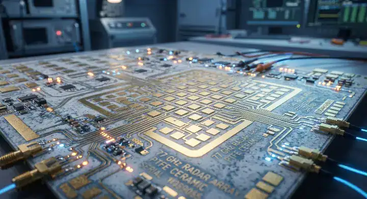
Quick Answer: RO3003 is a ceramic-filled PTFE PCB material delivering an ultra-low dissipation factor (Df) of 0.0010 at 10 GHz, making it mandatory for 77 GHz radar and Ka-band satellite applications. However, processing this pure PTFE laminate requires plasma desmear and sodium naphthalene treatments, increasing total fabrication costs by 2.3× compared to thermoset alternatives. Key takeaways:
To compare laminate families, electrical behavior, fabrication limits, and sourcing trade-offs in one place, use the complete PCB materials guide.
- The material offers an ultra-low Df of 0.0010 but requires expensive PTFE-specific chemical treatments.
- Astra MT77 can replace it in 80% of mmWave applications, cutting costs by over 50%.
- Hybrid stackups must use FEP bonding film or RO4450F at 315°C to prevent layer delamination.
- PTFE boards are not UL 94 V-0 rated because they lack standard flame-retardant properties.
Table of Contents
- What Is Rogers RO3003 and Why Is PTFE Still Used?
- What Electrical Properties Define RO3003 Performance?
- Why Does This PTFE Laminate Cost 2-3× More to Process?
- Which Radar and Satellite Designs Depend on This Material?
- How Does RO3003 Compare to Astra MT77 at mmWave?
- How Does the Substrate Differ from RO4350B Boards?
- How Do You Build a PTFE and FR-4 Hybrid Stackup?
- When Must You Use PTFE and When Can You Avoid It?
- How Do Fabricators Process High-Frequency Boards?
- How Will Non-PTFE Materials Reshape the Laminate Market?
Does your 77 GHz radar design require absolute signal fidelity? RO3003 provides unmatched signal integrity for millimeter-wave circuits but requires a massive fabrication premium. Designing an automotive radar board only to realize the PTFE processing costs destroy your budget is a common engineering mistake. High-frequency engineers often default to pure PTFE laminates without understanding the expensive sodium naphthalene treatments required to plate the vias. You can optimize your BOM by matching RO3003 to the exact components that mandate it, like the LNA first stage, while using an Astra MT77 non-PTFE mmWave laminate guide to handle the less demanding antenna feeds.
What Is Rogers RO3003 and Why Is PTFE Still Used?
RO3003 is a ceramic-filled, glass-free PTFE composite that maintains a highly stable dielectric constant of 3.00 up to 110 GHz. This specific resin system eliminates standard woven glass cloth to prevent the fiber weave effect, resulting in perfectly uniform signal propagation for advanced automotive radar. Because the material relies entirely on ceramic fillers for mechanical stability, it requires specialized handling during lamination.
The Anatomy of Ceramic-Filled PTFE
Fiber weave effect is a localized impedance variation caused by the physical gaps in standard glass cloth reinforcement. By removing the glass entirely, this substrate guarantees that high-frequency signals experience identical dielectric properties regardless of routing direction.
Look at the facts:
- Zero glass cloth eliminates periodic loading on microstrip lines.
- Z-axis CTE matches copper at 24 ppm/°C for via reliability.
- Ceramic fillers provide the required mechanical rigidity for panel processing.
This material formulation prevents phase shifting in advanced antenna arrays, resulting in highly accurate beam steering for autonomous vehicles.
Key Takeaway: Ceramic-filled PTFE eliminates the fiber weave effect completely, making it mandatory for highly phase-sensitive millimeter-wave applications. Bottom line: Specify glass-free laminates when designing 77 GHz antenna arrays to prevent signal skew and phase distortion.
What Electrical Properties Define RO3003 Performance?
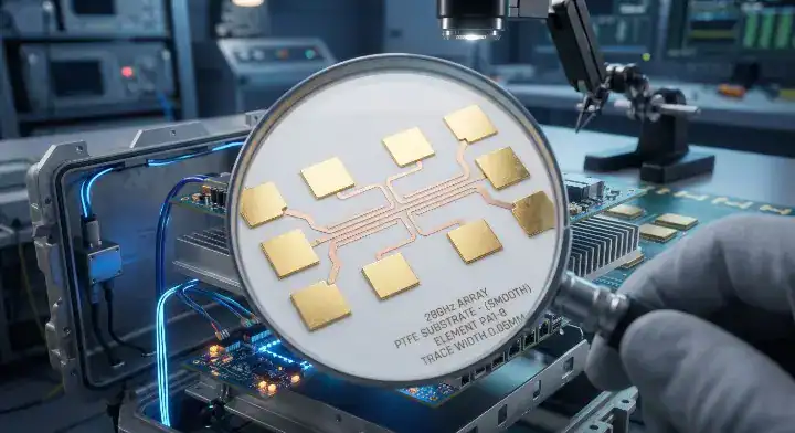
The material achieves a benchmark dissipation factor (Df) of 0.0010 at 10 GHz, significantly outperforming standard high-speed digital laminates and mid-loss RF substrates. This ultra-low loss profile minimizes signal attenuation across long transmission lines, which means engineers can stretch their link budgets further in W-band applications. Using standard FR-4 at these frequencies results in complete signal decay within millimeters.
Core Specifications for High Frequency
Moisture absorption is a physical metric defining how much water a laminate retains. At < 0.04%, this substrate resists environmental changes, keeping the dielectric properties locked in regardless of outdoor humidity.
Consider the specifications:
- Dk remains flat at 3.00 ±0.04 across the entire operating spectrum.
- Thermal conductivity sits at 0.50 W/mK, handling moderate amplifier loads.
- X/Y-axis CTE holds at 17 ppm/°C to maintain dimensional stability.
| Specification | RO3003 Value | Testing Condition |
|---|---|---|
| Dielectric Constant (Dk) | 3.00 ±0.04 | @ 10 GHz |
| Dissipation Factor (Df) | 0.0010 | @ 10 GHz |
| Moisture Absorption | < 0.04% | 48 hours |
Maintaining a moisture absorption rate below 0.05% prevents the board’s insertion loss from spiking during heavy rain or humid conditions.
Key Takeaway: The combination of an ultra-low Df and minimal moisture absorption makes this laminate the benchmark for outdoor millimeter-wave hardware. Bottom line: Rely on a Df of 0.0010 to close your link budget when designing W-band satellite links that must operate flawlessly in harsh weather.
Why Does This PTFE Laminate Cost 2-3× More to Process?
Processing RO3003 requires a fundamentally different cost structure than any FR-4-compatible material because of the intense chemical preparation required. Our PTFE line runs plasma desmear at $1,200 per lot, a step that does not exist for thermosets, and sodium naphthalene hole-wall treatment adds another $600 per lot. PTFE-specific drill bits cost $35 each versus $8 for standard carbide, and drill life on RO3003 averages 650 hits versus 2,200 on thermoset alternatives. Total processing cost on an equivalent 6-layer RF board runs approximately 2.3× higher, which means you pay a 129% premium for the PTFE performance.
Breaking Down the Fabrication Premium
A user on the Reddit PCB engineering forum recently asked, (1) “Why is RO3003 so expensive to process?” Using standard PCB fabrication techniques on pure PTFE results in immediate via plating failure because the resin repels copper. Specialized PTFE and RF PCB manufacturing services employ aggressive chemical etchants to modify the hole wall before metallization.
Look at the breakdown:
- Plasma desmear adds roughly $1,200 per production lot.
- Sodium naphthalene treatment requires isolated, dedicated chemical lines.
- Drill bit consumption triples compared to standard high-Tg laminates.
Fabrication costs scale exponentially with PTFE boards, making material selection a direct driver of the final unit price.
Key Takeaway: The raw laminate price only accounts for a fraction of the total cost; the specialized chemical processing drives the true expense of PTFE boards. Bottom line: Never budget a PTFE design using standard FR-4 fabrication multipliers; always calculate a 2.3× processing premium.
Which Radar and Satellite Designs Depend on This Material?
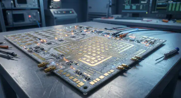
Advanced 77 GHz ADAS radar modules and Ka-band satellite LNBs rely completely on this ultra-low-loss substrate to keep noise figures below 2.0 dB. A recent 77 GHz ADAS radar module we built for an automotive Tier-1 used a 4-layer construction with two 10-mil RO3003 cores for the patch antenna array. The antenna traces measured 0.26 dB/inch insertion loss at 77 GHz, holding impedance at 50 Ω ±2.5% on the microstrip feed lines. The customer accepted the $85 unit cost premium at 500-piece volume because their LNA noise figure requirement mandated a Df of ≤ 0.0012.
Applications Requiring Absolute Low Loss
An engineer on the EEVBlog Forum inquired, (2) “When must I use PTFE and when can I avoid it?” You must use it when the receiver sensitivity dictates absolute minimum insertion loss prior to the first amplification stage.
Why does this matter?
- 77 GHz LNA first stages require the 0.0010 Df to maintain signal clarity.
- Ka-band satellite receivers demand glass-free laminates to prevent phase errors.
- W-band imaging systems operate at frequencies where thermosets simply fail.
| Application Type | Required Feature | Why It Demands PTFE |
|---|---|---|
| 77 GHz LNA Input | NF < 2.0 dB | Thermosets cause too much insertion loss |
| Ka-Band Satellite | Phase stability | Zero glass cloth prevents skew |
| W-Band Imaging | 110 GHz capability | Only PTFE maintains Dk stability |
Pushing frequencies past 77 GHz physically limits your material choices to pure PTFE composites.
Key Takeaway: Certain ultra-high-frequency applications hit a physical wall where no thermoset material can meet the stringent noise figure requirements. Bottom line: Reserve pure PTFE exclusively for LNA first stages and W-band receivers where paying the 2.3× cost premium is functionally required.
How Does RO3003 Compare to Astra MT77 at mmWave?
RO3003 delivers a superior Df of 0.0010 compared to Astra MT77’s 0.0017, but it lacks the glass reinforcement that makes Astra MT77 compatible with standard FR-4 fabrication lines. This difference means Astra MT77 can be processed identically to standard high-speed digital boards, skipping the costly plasma and sodium naphthalene treatments. For applications under 40 GHz, the 0.0007 difference in Df rarely justifies the massive cost penalty of PTFE.
PTFE Versus Thermoset Resin Systems
A designer on SierraConnect asked, (3) “Can Astra MT77 replace RO3003 at 77 GHz?” The answer is yes for the main antenna feed, but no for the highly sensitive LNA first stage. Understanding Astra MT77 processing advantages over PTFE allows you to split the BOM and save significant capital.
Consider the numbers:
- Astra MT77 supports standard carbide drill bits lasting over 2,000 hits.
- Thermosets support standard HDI laser drilling for microvias.
- PTFE requires mechanical drilling, limiting high-density interconnect options.
| Metric | Rogers RO3003 | Isola Astra MT77 |
|---|---|---|
| Df @ 10 GHz | 0.0010 | 0.0017 |
| Resin Base | Pure PTFE | Thermoset |
| Plasma Desmear | Required | Not Required |
| HDI Laser Drilling | Not Recommended | Fully Supported |
The thermoset architecture provides 80% of PTFE’s electrical performance at less than half the total fabrication cost.
Key Takeaway: The slight electrical advantage of PTFE is entirely offset by its severe manufacturing restrictions in standard commercial applications. Bottom line: Switch to Astra MT77 for all 28 GHz and 39 GHz 5G antennas to maintain performance while slashing fabrication costs.
How Does the Substrate Differ from RO4350B Boards?
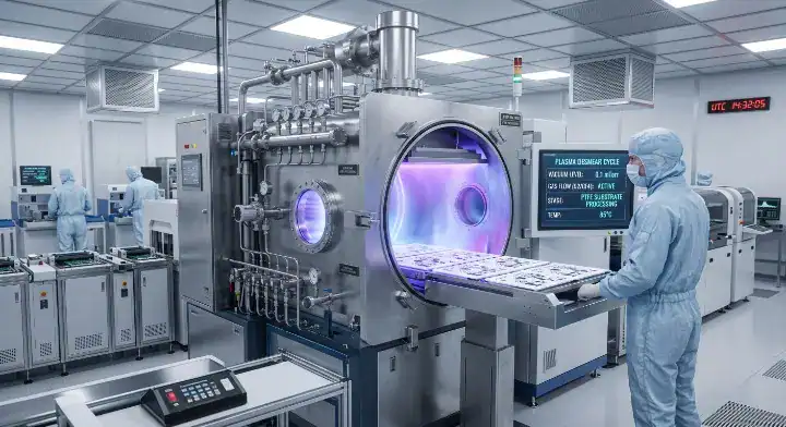
Unlike the hydrocarbon ceramic RO4350B which processes exactly like standard FR-4, this pure PTFE substrate requires specialized chemical etching before any via plating can occur. RO4350B holds a UL 94 V-0 flame retardant rating and features glass cloth reinforcement, which means it offers superior dimensional stability during multilayer lamination. PTFE boards lack this rating and warp easily if not handled with extreme precision.
Hydrocarbon vs Pure PTFE Processing
Many designers mistakenly group all high-frequency materials together. Reviewing RO4350B specifications and Dk trap avoidance reveals that hydrocarbon ceramics bridge the gap between FR-4 workability and RF performance, while PTFE sits strictly at the extreme high-end.
Here is the reality:
- RO4350B processes perfectly on standard continuous lamination presses.
- PTFE materials shift during pressing due to the lack of woven glass.
- RO4350B provides better thermal conductivity (0.69 W/mK) for power amplifiers.
Hydrocarbon ceramics dominate the Sub-6 GHz market specifically because they eliminate the headaches associated with PTFE fabrication.
Key Takeaway: RO4350B provides a highly stable, FR-4 compatible platform for Sub-6 GHz, whereas PTFE is strictly reserved for fragile mmWave applications. Bottom line: Never specify PTFE for Sub-6 GHz power amplifier boards; use RO4350B to secure better thermal dissipation and standard FR-4 pricing.
How Do You Build a PTFE and FR-4 Hybrid Stackup?
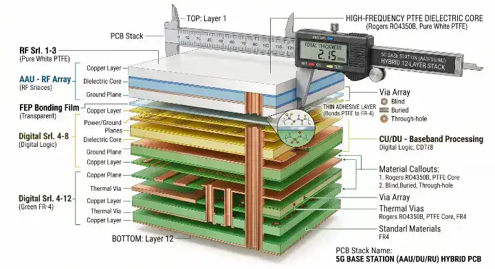
Building a hybrid stackup requires laminating the PTFE RF layers to the FR-4 digital layers using specialized FEP bonding films or RO4450F prepreg at temperatures reaching 315°C. You cannot use standard FR-4 prepreg to bond PTFE directly, because the chemical incompatibility results in severe delamination after only a few thermal cycles. This extreme pressing temperature requires specialized vacuum presses that many standard fabrication shops simply do not own.
Preventing Interface Failure During Thermal Cycles
A manufacturer on the Electronics Stack Exchange asked, (4) “How do I build a RO3003 + FR-4 hybrid without delamination?” We laminated the board at 315°C for 20 minutes under vacuum using FEP bonding film because direct FR-4 prepreg fails immediately. We commonly integrate I-Tera MT40 as the digital layer in RF hybrid stackups along with FR408HR for power layers in hybrid builds to balance the mechanical stress.
Look at the required process:
- FEP bonding film acts as the mandatory adhesive bridge.
- Press temperatures must exceed 300°C to activate the bond.
- Stackups must remain completely symmetric to prevent Z-axis warpage.
| Layer Type | Recommended Material | Pressing Requirement |
|---|---|---|
| RF Core | RO3003 | Requires plasma prep |
| Bonding Layer | FEP Film / RO4450F | 315°C vacuum press |
| Digital Core | I-Tera MT40 / FR408HR | Standard processing |
Properly engineered hybrid stackups isolate the expensive PTFE material strictly to the layers carrying the mmWave signals.
Key Takeaway: Hybrid integration allows engineers to leverage PTFE’s electrical benefits without paying for it across all 10 or 12 layers of a complex board. Bottom line: Always specify FEP bonding film when mating PTFE cores to FR-4 layers to guarantee the board survives standard thermal cycling.
When Must You Use PTFE and When Can You Avoid It?
You must use PTFE for 77 GHz LNA first stages requiring noise figures under 2 dB, but you can confidently avoid it for 28 GHz 5G antennas where thermosets easily meet the link budget. The physical difference in insertion loss at 28 GHz between PTFE (0.25 dB/inch) and thermosets (0.31 dB/inch) is negligible for most commercial designs, which means you are throwing money away by over-specifying.
The Application Decision Matrix
A hardware architect on the All About Circuits Forum inquired about the specific cutoff point. We advise checking the exact decibel margins in your channel simulation before defaulting to the most expensive material on the market.
What is the bottom line?
- 77 GHz radar antenna feeds under 3 inches can safely use Astra MT77.
- 5G AAU antennas operate perfectly on mid-to-high grade thermosets.
- Ka-band satellite LNBs strictly require the 0.0010 Df of pure PTFE.
Switching from PTFE to a high-grade thermoset for short-run antenna feeds immediately slashes production costs without breaking the RF link budget.
Key Takeaway: Over-engineering a PCB with PTFE when a thermoset would suffice is the most common cause of budget overruns in RF hardware development. Bottom line: Calculate your exact insertion loss tolerance at your target frequency; if a thermoset meets the budget, drop the PTFE requirement immediately.
How Do Fabricators Process High-Frequency Boards?
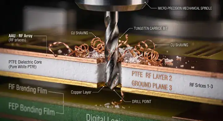
Fabricators process high-frequency PTFE boards using dedicated plasma chambers and isolated chemical lines to prevent contamination of standard production batches. Because PTFE is chemically inert, it vehemently resists copper adhesion, requiring aggressive sodium naphthalene to create microscopic pores on the hole walls before electroless copper deposition. Standard shops lacking this dedicated infrastructure will suffer massive via voiding and plating separations.
Navigating Complex Chemical Treatments
You cannot send a PTFE board to a prototype shop that only handles standard FR-4. Furthermore, because PTFE is not halogen-free, it requires careful compliance checking against European standards, heavily contrasting with a halogen-free PCB specification guide.
Consider the fabrication steps:
- Panels run through isolated wet process lines to prevent cross-contamination.
- X-ray registration occurs after every lamination cycle to correct dimensional shifting.
- Routing requires specialized bits and slower feed rates to prevent material smearing.
The inert nature of PTFE demands violent chemical modifications just to accept a standard copper via plating.
Key Takeaway: PTFE fabrication is a niche specialty requiring heavy capital investment in plasma and chemical line infrastructure. Bottom line: Verify that your chosen fabrication partner has in-house plasma desmear capabilities before submitting any PTFE gerber files.
How Will Non-PTFE Materials Reshape the Laminate Market?
Non-PTFE materials are rapidly capturing the 28-39 GHz 5G market by offering 80% of PTFE’s electrical performance at less than half the manufacturing cost. As thermoset resin technology advances, products like Astra MT77 are pushing the boundary of what non-PTFE materials can achieve, threatening PTFE’s dominance in everything except extreme W-band applications. This shift means hardware developers can finally deploy massive MIMO arrays without the paralyzing costs of pure Teflon substrates.
The Future of Millimeter-Wave Fabrication
The industry is moving aggressively toward materials that support HDI architectures. Because PTFE severely limits laser drilling and microvia formation, engineers are forced to abandon it when designing ultra-dense digital-RF hybrid boards.
Look at the trajectory:
- Thermosets now comfortably support 77 GHz automotive radar feeds.
- HDI compatibility makes non-PTFE materials the default for dense 5G RUs.
- PTFE will eventually retreat to niche aerospace and specialized military applications.
The inability of PTFE to support high-density laser microvias makes it incompatible with the next generation of highly integrated RF transceivers.
Key Takeaway: The fabrication advantages of thermoset materials are driving a massive industry shift away from PTFE in all but the most extreme high-frequency designs. Bottom line: Transition your new millimeter-wave designs to thermoset platforms to secure HDI compatibility and long-term supply chain stability.
Frequently Asked Questions (FAQs)
Can Astra MT77 replace RO3003 at 77 GHz? Yes, but only for the antenna feed networks. Short trace runs under 3 inches will function perfectly on Astra MT77, but the highly sensitive LNA first stage still requires the 0.0010 Df of pure PTFE to keep noise figures under 2.0 dB.
Why is RO3003 so expensive to fabricate? Because the material is chemically inert. It demands $1,200 plasma desmear treatments, $600 sodium naphthalene hole-wall preparations, and burns through specialized drill bits three times faster than standard thermoset laminates.
Is RO3003 halogen-free and UL 94 rated? No, it is neither. The material does not contain the necessary flame retardants to pass UL 94 V-0 testing, and its chemical composition does not meet European halogen-free compliance standards for commercial 5G deployment.
How do you bond RO3003 to FR-4 layers in a hybrid stackup? You must use FEP bonding film or RO4450F prepreg. The stackup requires a specialized vacuum press capable of reaching 315°C; using standard FR-4 prepreg against PTFE will cause immediate delamination.
When is a PTFE substrate completely unavoidable? Yes, it is unavoidable when designing Ka-band satellite LNBs, W-band imaging systems, and 77 GHz LNA inputs where the signal link budget strictly dictates an insertion loss profile that thermosets cannot physically achieve.
Selecting the right high-frequency laminate dictates the financial success of your entire RF hardware deployment. If you need engineering assistance designing a PTFE hybrid stackup or calculating the true fabrication costs of your next mmWave project, contact us today for a free DFM review. We provide exact material mapping to guarantee your RF performance hits the mark on the first pass without destroying your budget. At QueenEMS, we turn complex high-frequency designs into reliable, scalable hardware.
Written by the QueenEMS Engineering Team
Upload your files today · Free DFM check before production · Ship worldwide
Get your PCB prototypes in as fast as 24 hours. We handle FR4, Rogers, and Flex up to 60 layers — free prototypes for 2–4 layer boards, no minimum order.
Just upload your Gerber + BOM — we source every part, assemble, and inspect (AOI + X‑Ray) so you don't have to chase suppliers. Boards ship in as fast as 24 hours.