
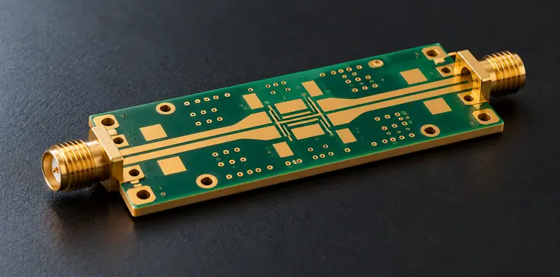
Quick Answer: Specify an RF PCB PIM test by its test object, tone frequencies and powers, reference plane, measured intermodulation product and test condition. A laminate certificate identifies material evidence; it does not report intermodulation from a finished board or assembled RF path. Set the acceptance limit on the same stated measurement basis, with external interference and powered-fixture residual addressed in the test plan.
Two reports can show the same unit while describing different objects and stimulus conditions. Before using either to release a board order, ask what was connected between the measurement boundaries. That question determines whether you have a coupon comparison, a board-path result or evidence about an assembled product.
What does an RF PCB PIM test measure?
A two-tone passive intermodulation test applies two RF signals and measures unwanted intermodulation products generated in the passive path under test. The result belongs to that connected object and its conditions. It is a different quantity from impedance or insertion loss, so those measurements cannot replace the specified PIM evidence.
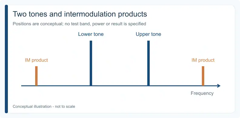
For tones at f₁ and f₂, the third-order products include 2f₁ − f₂ and 2f₂ − f₁. The Kaelus PIM guideline, ©2017, illustrates these products. As a constructed frequency-arithmetic example only, tones at 900 MHz and 910 MHz place those products at 890 MHz and 920 MHz. These are not recommended PCB test frequencies or measured results.
The IEC 62037-1:2025 public abstract describes two-transmitter measurement methods for passive RF and microwave components. It also states that the series does not address long-term product reliability. Its public scope supports the measurement distinction here; it supplies no verified PCB-specific coupon acceptance requirement.
Why can’t a laminate certificate supply a board result?
A laminate certificate describes the material and properties within its declared scope. A PIM result describes a powered test object, connected through a specified measurement path. Moving from material evidence to a finished-board or assembled-path acceptance decision therefore requires evidence for that object, rather than treating the certificate as its test report.
That distinction is an engineering inference from the measurement sources, applied here to a PCB order. The delivered conductor structure, plated features, launches and mounted connections can fall outside the material certificate's scope. No ranking or numerical effect for those possible contributions is established here.
Keep the as-built stackup identified—including hybrid high-frequency stackup details where materials are mixed—so the tested construction can be related to the ordered board. Material identity remains useful evidence, alongside the PIM report. A material name alone cannot identify the tested launch, the connector configuration or the tone power applied to the object.
Which test object should the PIM report cover?
Choose the object that answers the release decision: a representative fabrication coupon, a bare-board RF structure through a defined launch, or an assembled RF path. Each includes different conductors and connections. State those boundaries before testing so a result is used for the object it represents, with its representativeness and exclusions recorded.
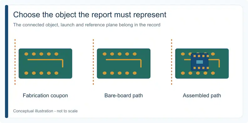
This test-object map is a suggested engineering/procurement aid and editorial synthesis. It transfers component/system measurement principles to order review; it is not a standard's mandated object selection.
| Test object | Inside the result | Decision it can support | Boundary to declare |
|---|---|---|---|
| Fabrication coupon | Coupon structure and launch | Comparison using the same representative coupon design | Design, launch, reference plane and lot relationship |
| Bare-board RF structure | Production-board path with its fixture/launch | Result for that connected board path | Fixture, launch, plane and powered residual plan |
| Assembled RF path | Board, mounted parts and connected RF hardware | Behavior of the specified assembly | Configuration, connectors, load and condition |
A coupon result does not independently characterize the mounted product, and an assembly result does not isolate the PCB's contribution. Treat RF PCB fabrication and PIM measurement as separately scoped deliverables: name who performs the measurement and on which object. Neither this table nor a fabrication quotation establishes a PIM testing service.
Where should tone power and frequencies be defined?
State both tone frequencies and each tone's power at a named DUT reference plane, together with the measured intermodulation product and direction. A source setting alone can leave losses before the object unaccounted for. The agreed stimulus must respect the DUT's power capability and match the basis used to set the acceptance limit.
The Rohde & Schwarz application card, version 01.00, September 2013, illustrates calibration of tone powers at the DUT plane and thermal settling in a duplex-filter setup. Use that principle to identify the plane; its instrument performance figures are not PCB acceptance values.
The Kaelus guideline shows measured PIM changing with applied tone power, so results taken at different powers are not automatically comparable. Record the unit basis as well: dBm and dBc are different display conventions. When a report uses dBc, require its carrier-reference convention to be stated. Do not compare the number with a differently expressed limit or extrapolate an unmeasured power condition.
To obtain a quotation and free DFM review, send the Gerber files, stackup and fabrication drawing. Add the BOM when assembly is requested. If release depends on PIM, include the intended object, tones, power and limit so project feasibility and scope can be reviewed.
How do external noise and fixture residual differ?
A transmit-off noise-floor check identifies external receive-band interference; it does not measure residual PIM produced by a powered fixture. The test path can include cables, launches and a load as well as the DUT. Request separate records for interference and the powered setup so an unexpected result is not automatically attributed to the board.
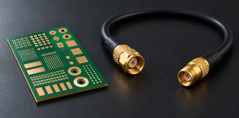
Anritsu’s noise-floor instructions explicitly turn both transmitters off, so the receiver sees only external signals. Its separate swept-PIM setup connects a test cable, the DUT and a low-PIM load or antenna. An interference-free receive band therefore answers a different question from the powered path’s behavior with RF applied.
As a suggested planning step, ask the measurement provider how it establishes and records the residual of the powered path, and how that record relates to the actual fixture and connection state. Agree how inconclusive separation will be reported. No numerical residual margin or subtraction method is prescribed here; a clean transmit-off trace alone cannot supply that evidence.
How do swept and dynamic tests change what a pass means?
Frequency coverage and mechanical condition are separate choices. A fixed-frequency test can pass while multiple PIM sources cancel at that point; a swept or multi-frequency test can expose that variation. A static test holds connections still, while a dynamic test applies an agreed physical stimulus during observation. Record both choices in the report.
Anritsu's swept-PIM explanation describes the vector addition of PIM signals and possible cancellation. Swept or multiple-frequency testing can expose variation; one arbitrary sweep is not shown to capture every case.
The IEC 2025 abstract notes frequency dependence and reporting the maximum measured PIM over the test duration. State the duration and applicable frequency range rather than retaining only a favorable point. If a dynamic condition is relevant, define it for the actual object. A cell-site procedure involving coax connections is not authorization to tap, bend or otherwise stress a PCB in the same way.
Can two PIM reports support the same acceptance decision?
Two reports support a like-for-like decision only when their objects, stimulus, measurement boundaries and conditions match the agreed comparison basis. Resolve missing definitions before comparing their displayed values. Where the objects differ, retain each report for its own evidence role rather than using a better-looking number to replace the required test.
Use this report-comparability checklist as a suggested engineering/procurement aid and editorial synthesis:
- Match the object, construction revision, configuration and representativeness.
- Match f₁/f₂, each tone's DUT-plane power, IM order and forward/reverse direction.
- Identify fixture, launch, load, transmit-off interference record and powered residual record.
- Match static, swept or dynamic conditions, range, duration and reported maximum.
- Confirm units, carrier-reference convention, customer limit and decision basis.
Hypothetical comparison: Report A describes a static coupon with fixed tones and a coax launch. Report B describes a swept production-board path through a different fixture. Even if their units match, they describe different objects and conditions. Classify the pair as comparable, missing a definition, or different in scope before making an acceptance decision.
Frequently Asked Questions
Is there a universal PCB PIM pass limit?
No. Set the limit from the application requirement on a declared frequency, tone-power, intermodulation and unit-reference basis. A number copied from another RF system does not establish acceptance for your object. Keep the requirement and reported measurement conditions together.
Must every RF PCB use the same tone power?
No. Agree a stimulus appropriate to the application and within the DUT's power capability. State each tone's power at the reference plane. Measurements made at other powers are not automatically interchangeable, and high-power levels used for cell-site cables and antennas are not a universal PCB setting.
Can a fixed-frequency pass hide a PIM problem?
Yes. Multiple PIM contributions can combine out of phase at a particular frequency and produce an apparent pass. Swept or multiple-frequency characterization can reveal frequency dependence, but the chosen coverage still needs to suit the actual requirement.
Does an assembled-path test always replace a coupon test?
No. A coupon can support a representative fabrication comparison, while an assembled-path test includes mounted parts and connections. Select the evidence required by the decision. An assembly result alone cannot assign its measured PIM contribution specifically to the bare PCB.
QueenEMS has more than 10 years of experience. Ask for a quotation and a free DFM review: send the fabrication drawing, stackup and Gerber data with the PIM requirement and its test-object definition. For assembly requests, also supply the BOM. Confirm who provides the measurement evidence before release.
Upload your files today · Free DFM check before production · Ship worldwide
Get your PCB prototypes in as fast as 24 hours. We handle FR4, Rogers, and hybrid boards, with standard builds up to 24 layers and higher layer counts subject to engineering review — free prototypes for 2–4 layer FR-4 boards, no minimum order.
Just upload your Gerber + BOM — we source every part, assemble, and inspect (AOI + X‑Ray) so you don't have to chase suppliers. PCB assembly typically takes 5–8 working days once all components are in stock. The confirmed delivery schedule is subject to your quotation.